
User manual
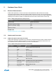

Pin on EXT1 Function Description
12 TWI_SCL I
2
C SCL
13 UART_TX UART TX
14 UART_RX UART RX
15 SPI_SS_A SPI SS
16 SPI_MOSI SPI MOSI
17 SPI_MISO SPI MISO
18 SPI_SCK SPI Clock
19 GND Ground
20 VCC Target supply voltage
Related Links
Xplained Pro Standard Extension Header on page 7
5.2.2. Current Measurement Header
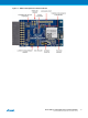
Current Measurement header J101 can be used to measure the current consumed by the ATBTLC1000
module using an ammeter. The two 0Ω resistors R112 and R113 can be removed to measure the current
consumed by individual power rails VDDIO and VBAT respectively by soldering in wires for an ammeter.
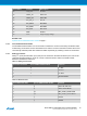
5.2.3. Debug Connectors
Debug I
2
C (J104) and Extension port (J105) are not mounted on the board. Extension port J105 can be
configured as Debug UART or as SPI to connect to external sensors. Refer to the ATBTLC1000-
MR110CA datasheet for reference.
Table 5-3 Debug I
2
C Connector
Pin on I
2
C connector Pin on ATBTLC1000 module Function
1 8 I
2
C SCL
2 1 Ground
3 7 I
2
C SDA
4 - Not Connected
Table 5-4 Extension Port
Pin on Extension Port Pin on ATBTLC1000 module Function
1 4 UART RX/ SPI SCK
2 5 UART TX/SPI MOSI
3 21 DBG_UART_RX/SPI SSN
4 23 DBG_UART_TX/SPI MISO
5 1 Ground
6 1 Ground
Atmel ATBTLC1000 Xplained Pro [USER GUIDE]
Atmel-42538B-BTLC1000-Xplained-Pro_User Guide-11/2015
10