
User manual
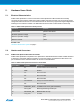
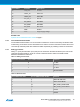

Table 4-2 Xplained Pro Standard Extension Header
Pin number Name Description
1 ID Communication line to the ID chip on an extension board
2 GND Ground
3 ADC(+) Analog to digital converter, alternatively positive part of differential
ADC
4 ADC(-) Analog to digital converter, alternatively negative part of differential
ADC
5 GPIO1 General purpose I/O
6 GPIO2 General purpose I/O
7 PWM(+) Pulse width modulation, alternatively positive part of differential
PWM
8 PWM(-) Pulse width modulation, alternatively negative part of differential
PWM
9 IRQ/GPIO Interrupt request line and/or general purpose I/O
10 SPI_SS_B/
GPIO
Slave select for SPI and/or general purpose I/O
11 I
2
C_SDA Data line for I
2
C interface. Always implemented, bus type.
12 I
2
C_SCL Clock line for I
2
C interface. Always implemented, bus type.
13 UART_RX Receiver line of target device UART
14 UART_TX Transmitter line of target device UART
15 SPI_SS_A Slave select for SPI. Should preferably be unique.
16 SPI_MOSI Master out slave in line of serial peripheral interface. Always
implemented, bus type.
17 SPI_MISO Master in slave out line of serial peripheral interface. Always
implemented, bus type.
18 SPI_SCK Clock for serial peripheral interface. Always implemented, bus type.
19 GND Ground
20 VCC Power for extension board
Atmel ATBTLC1000 Xplained Pro [USER GUIDE]
Atmel-42538B-BTLC1000-Xplained-Pro_User Guide-11/2015
8