
User manual

5. Hardware Users Guide
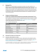
5.1. Electrical Characteristics
ATBTLC1000 Xplained Pro can be connected to several Xplained Pro MCU boards and manually
connected to other hardware. Xplained Pro MCU board(s) that does not have 3.3V as it's primary target
voltage will read all ID devices on connected extensions to check if they support the target voltage before
enabling it to the extension headers. The table below shows the static content written in the ID chip.
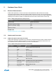
Table 5-1 ATBTLC1000 Xplained Pro ID Chip Content
Data field Content
Product name ATBTLC1000-XPRO
Minimum operation voltage 1.8V
Maximum operation voltage 3.6V
Maximum current 10mA
Related Links
Hardware Identification System on page 7
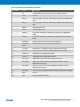
5.2. Headers and Connectors
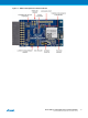
5.2.1. ATBTLC1000 Xplained Pro Extension Header
ATBTLC1000 Xplained Pro implements one Xplained Pro Standard Extension Header marked with EXT1
in silkscreen. This header makes it possible to connect the board to an Xplained Pro MCU board. The
pin-out definition for the extension header can be seen in the table below.
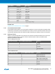
Table 5-2 ATBTLC1000 Xplained Pro Extension Header EXT1
Pin on EXT1 Function Description
1 ID Communication line to the ID chip
2 GND Ground
3 NC Not Connected
4 NC Not Connected
5 NC Not Connected
6 GPIO/WAKE Always-on External Wakeup
7 NC Not Connected
8 PWM-/RTC_CLKP 32.768kHz RTC Clock (optional feature)
9 GPIO_MS1 Mixed signal/Analog interface pin
10 GPIO/CHIP_EN Master Enable for chip
11 TWI_SDA I
2
C SDA
Atmel ATBTLC1000 Xplained Pro [USER GUIDE]
Atmel-42538B-BTLC1000-Xplained-Pro_User Guide-11/2015
9