
User manual

Atmel SAM4S Xplained Pro [USER GUIDE]
Atmel-42075B-MCU-Atmel SAM4S Xplained Pro-USER GUIDE-03/2013
8
extensions to Xplained Pro MCU boards and to access the pins of the target MCU on Xplained Pro MCU board
directly.
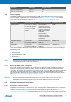
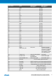
Table 3.4. Xplained Pro extension header
Pin number Name Description
1 ID Communication line to the ID chip on extension board.
2 GND Ground
3 ADC(+) Analog to digital converter , alternatively positive part of differential
ADC
4 ADC(-) Analog to digital converter , alternatively negative part of
differential ADC
5 GPIO1 General purpose IO
6 GPIO2 General purpose IO
7 PWM(+) Pulse width modulation , alternatively positive part of differential
PWM
8 PWM(-) Pulse width modulation , alternatively positive part of differential
PWM
9 IRQ/GPIO Interrupt request line and/or general purpose IO.
10 SPI_SS_B/GPIO Slave select for SPI and/or general purpose IO.
11 TWI_SDA Data line for two wire interface. Always implemented, bus type.
12 TWI_SCL Clock line for two wire interface. Always implemented, bus type.
13 USART_RX Receiver line of Universal Synchronous and Asynchronous serial
Receiver and Transmitter
14 USART_TX Transmitter line of Universal Synchronous and Asynchronous
serial Receiver and Transmitter
15 SPI_SS_A Slave select for SPI. Should be unique if possible.
16 SPI_MOSI Master out slave in line of Serial peripheral interface. Always
implemented, bus type
17 SPI_MISO Master in slave out line of Serial peripheral interface. Always
implemented, bus type
18 SPI_SCK Clock for Serial peripheral interface. Always implemented, bus
type
19 GND Ground
20 VCC Power for extension board
3.4.2 Xplained Pro LCD connector
The LCD connector provides the ability to connect to display extensions that have a parallel interface. The
connector implements signals for a MCU parallel bus interface and a LCD controller interface as well as signals
for a touchcontroller. The connector pin-out definition is shown in Table 3.5, “Xplained Pro LCD connector”.
Note that usually only one display interface is implemented, either LCD controller or the MCU bus interface.
A FPC/FFC connector with 50 pins and 0.5mm pitch is used for the LCD connector. The connector
(XF2M-5015-1A) from Omron is used on several designs and can be used as a reference.
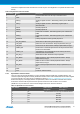
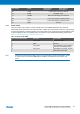
Table 3.5. Xplained Pro LCD connector
Pin number Name RGB interface
description
MCU interface
description
1 ID Communication line to ID chip on extension board.
2 GND Ground
3 D0 Data line
4 D1 Data line
5 D2 Data line
6 D3 Data line