
User Manual

BM62/64
Preliminary
DS60001403C-Page 10
2017 Microchip Technology Inc.
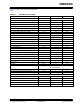
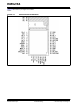
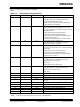
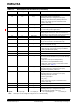
TABLE 1-2: BM62 MODULE PIN DESCRIPTION (CONTINUED)
Legend: I= Input pin O= Output pin I/O= Input/Output pin P= Power pin
Note: All I/O pins can be configured using the UI tool, a Windows utility.
Pin No
Pin Type
Pin Name
Description
17
-
NC
No connection
18
I/O
P0_1
Configurable control or indication pin
(Internally pulled-up, if configured as an input)
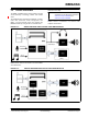
• FWD key when Class 2 RF (default), active-low
• Class 1 Tx control signal for external RF Tx/Rx
switch, active-high
19
P
VDD_IO
I/O positive supply. Do not connect, for internal use
only
20
P
ADAP_IN
5V power adapter input, used to charge the battery in
the Li-Ion battery power applications
21
P
BAT_IN
Power Supply input.
Voltage range: 3.2V to 4.2V. Source can either be a
Li-Ion battery or any other power rail on the host board
22
P
AMB_DET
Analog input for ambient temperature detection
23
P
GND
Ground reference
24
P
SYS_PWR
System power output derived from ADAP_IN or
BAT_IN. Do not connect, for internal use only
25
P
BK_OUT
1.8V buck regulator output. Do not connect to other
devices. For internal use only
26
I
MFB
• Multi-Function Button and power-on key
• UART RX_IND, active-high (used by host MCU to
wakeup the Bluetooth system)
27
I
LED1
LED driver 1
28
I
LED2
LED driver 2
29
I/O
P2_4
System configuration pin along with P2_0 and EAN
pins used to set the module in any one of the following
three modes:
• Application mode (for normal operation)
• Test mode (to change EEPROM values)
• Write Flash mode (to load a new firmware into the
module), refer to Table 5-1
30
I/O
P0_2
Configurable control or indication pin
(Internally pulled-up, if configured as an input)
Play/Pause key (default), active-low
31
I/O
P0_3
Configurable control or indication pin
(Internally pulled-up, if configured as an input)
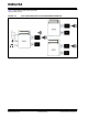
• REV key (default), active-low
• Buzzer signal output
• Out_Ind_2
• Class 1 Rx Control signal of external RF Tx/Rx
switch, active-high
32
I/O
HCI_TXD
HCI UART data output
33
I/O
HCI_RXD
HCI UART data input
34
I/O
P0_5
Configurable control or indication pin
(Internally pulled-up, if configured as an input)
Volume-down key (default), active-low