
User Manual


BM62/64
Preliminary
DS60001403C-Page 14
2017 Microchip Technology Inc.
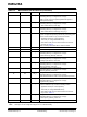
TABLE 1-3: BM64 MODULE PIN DESCRIPTION (CONTINUED)
Pin No
Pin Type
Pin Name
Description
29
I/O
P3_7
Configurable control or indication pin
(Internally pulled-up, if configured as an input)
UART TX_IND, active-low (used by Bluetooth system to
wakeup the host MCU)
30
I/O
P3_5
Configurable control or indication pin
(Internally pulled-up, if configured as an input)
• Slide switch detector, active-high
31
I/O
P0_0
Configurable control or indication pin
(Internally pulled-up, if configured as an input)
• Slide switch detector, active-high, Out_Ind_0
32
I
EAN
External address bus negative
System configuration pin along with the P2_0 and P2_4 pins
used to set the module in any one of these modes:
• Application mode (for normal operation)
• Test mode (to change EEPROM values)
• Write Flash mode (to load a new firmware into the mod-
ule) refer to Table 5-1
Flash: must be pulled-down with 4.7 kOhm to GND
33
I/O
DM
Differential data-minus USB
34
I/O
DP
Differential data-plus USB
35
I/O
P0_5
Configurable control or indication pin
(Internally pulled-up, if configured as an input)
Volume-down key (default), active-low
36
I/O
P3_0
Configurable control or indication pin
(Internally pulled-up, if configured as an input)
Auxiliary input detector, active-low
37
I/O
P3_1
Configurable control or indication pin
(Internally pulled-up, if configured as an input)
REV key (default), active-low
38
I/O
P3_3
Configurable control or indication pin
(Internally pulled-up, if configured as an input)
FWD key (default), active-low
39
I/O
P3_6
Configurable control or indication pin
(Internally pulled-up, if configured as an input)
Multi-SPK Master/Slave mode control (firmware dependent)
40
I/O
P0_2
Configurable control or indication pin
(Internally pulled-up, if configured as an input)
Play/Pause key (default)
41
I/O
P2_0
System configuration pin along with P2_4 and EAN pins used
to set the module in any one of the following modes:
• Application mode (for normal operation)
• Test mode (to change EEPROM values)
• Write Flash mode (to load a new firmware into the mod-
ule), refer to Table 5-1
42
I/O
P2_7
Configurable control or indication pin
(Internally pulled-up, if configured as an input)
Volume-up key (default), active-low
43
P
GND
Ground reference
Legend: I= Input pin O= Output pin I/O= Input/Output pin P= Power pin
Note: All I/O pins can be configured using the UI tool, a Windows utility.