
User Manual


BM62/64
Preliminary
DS60001403C-Page 40
2017 Microchip Technology Inc.
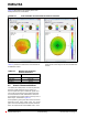
Figure 6-2 illustrates the 3D radiation pattern of the
PCB printed antenna at 2441 MHZ.
FIGURE 6-2: PCB ANTENNA 3D RADIATION PATTERN AT 2441 MHZ
Table 6-1 provides the PCB Antenna characteristics of
the BM62/64 module.
tion. For the best range performance, keep all external
metal at least 15 mm away from the on-board PCB trace
antenna.
TABLE 6-1: BM62/64 PCB ANTENNA
CHARACTERISTICS
Parameter
Values
Frequency
2400 MHz to 2480 MHz
Peak Gain
1.927 dBi
Efficiency
73.41%
6.2 Module Placement Guidelines
For a Bluetooth-enabled product, the antenna placement
affects the overall performance of the system. The
antenna requires free space to radiate RF signals and it
must not be surrounded by the ground plane. Microchip
recommends that the areas underneath the antenna on
the host PCB must not contain copper on the top, inner, or
bottom layers, as illustrated in Figure 6-1.
A low-impedance ground plane will ensure the best radio
performance (best range, lowest noise). The ground
plane can be extended beyond the minimum recommen-
dation, as required for the main PCB EMC noise reduc-