
User Manual


BM62/64
Preliminary
2017 Microchip Technology Inc.
DS60001403C-Page 53
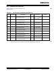
Figure 8-3 illustrates the timing diagram of the audio
interface.
FIGURE 8-3: AUDIO INTERFACE TIMING DIAGRAM
Table 8-10 provides the timing specifications of the
audio interface.
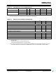
TABLE 8-10: AUDIO INTERFACE TIMING SPECIFICATIONS
PARAMETER
SYMBOL
MIN
TYP
MAX
UNIT
SCLK0 duty ratio
d
SCLK
—
50
—
%
SCLK0 cycle time
t
SCLKCY
50
—
—
ns
SCLK0 pulse width high
t
SCLKCH
20
—
—
ns
SCLK0 pulse width low
t
SCLKCL
20
—
—
ns
RFS0 setup time to SCLK0 rising edge
t
RFSSU
10
—
—
ns
RFS0 hold time from SCLK0 rising edge
t
RFSH
10
—
—
ns
DR0 hold time from SCLK0 rising edge
t
DH
10
—
—
ns
Note: Test Conditions: Slave Mode, f
s
= 48 kHz, 24-bit data and SLK0 period = 256 f
s
.