
User`s guide


Hardware
© 2008 Microchip Technology Inc. DS51700A-page 25
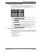
4.2 DEBUG FUNCTIONAL OVERVIEW
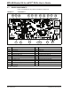
The block diagram shown in illustrates the debugging/programming operation of the
starter kit.
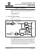
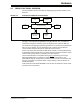
FIGURE 4-3: STARTER KIT DEBUG BLOCK DIAGRAM
The starter kit, with its built-in debugger/programmer, provides an all-in-one solution for
debugging and programming applications using MPLAB IDE. Also, no additional
external power supply is needed as power is supplied by the host PC’s USB port.
The starter kit's debugging/programming operations are controlled by a PIC18F67J50
MCU running at 48 MHz. The PIC18F67J50's built-in USB engine provides the
communications interface between the starter kit and the host PC.
Power to the starter kit is provided via USB whose nominal 5 volt unregulated supply
is regulated by a Microchip MC1727 3.3 volt low-dropout (LDO) linear regulator. Proper
starter kit main system power is indicated by the green LED ‘D1’.
The PIC18F67J50 MCU accomplishes debugging or programming of the target
dsPIC33FJ256GP506 by controlling the target’s MCLR
, PGC1/EMUC1, and
PGD1/EMUD1 signals. Target power is switched on/off via a low V
CE saturation PNP
transistor configured as a high-side switch. Target clocking is also provided by the
PIC18F67J50 MCU.
A Microchip 25LC010A serial EEPROM is used to store the starter kit’s serial number
and debug control information.
PIC18F67J50 Device
Status
LEDs
dsPIC33F
Device
USB Mini-B
Jack
Serial EEPROM
25LC010A
3.3V LDO
Regulator
12 MHz
Crystal
SPI
ICSP™