
User Manual

User Manual Page 6 of 12
SMSC CONFIDENTIAL
Revision 0.1 (8.26.2011)
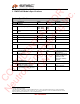
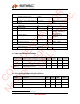
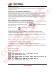
3.3. Pin out at PCI Express interface connector
The pin listing is shown here below:
Pin Number
Pin Name
I/O
Description
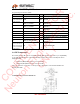
2, 24, 39, 41, 52 +3V3_PCIE PWR 3.3V Regulated input from PCIe
4, 9, 15, 18, 21,
26, 27, 29, 34, 35,
37, 40, 43, 50
GND GND Ground
3 GPIO_12_COEX1 I/O
Configurable. Please refer to the DARR83
datasheet
5 GPIO_13_COEX2 I/O
Configurable. Please refer to the DARR83
datasheet
20 GPIO_5_W_DISABLEN I/O
Configurable. Please refer to the DARR83
datasheet
22 NC NOT CONNECTED
36 DM ANA USB D-
38 DP ANA USB D+
42 GPIO_7_LED_WWAN# I/O
Configurable. Please refer to the DARR83
datasheet
46 GPIO_6_LED_WPAN#
I/O
Configurable. Please refer to the DARR83
datasheet
1, 6, 7, 8, 10, 11,
12, 13, 14, 16, 17,
19, 23, 25, 28, 30,
31, 32, 33, 44, 45,
47, 48, 49, 51
NC NOT CONNECTED
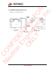
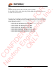
3.4. RF Connections
The module provides RF connectors (Hirose U.FL-R-SMT (CL No. 331-0471-0) or equivalent)
for use with external antennas. RX and TX diversity antennas are used to avoid dropouts due to
multipath fading.
Antenna A (Main) RF Connector J1 on the module
Antenna B (AUX) RF Connector J2 on the module
Only ‘one’ antenna is selected for use at any one time, through the on-board Transmit-Receive/
Diversity RF switch.
Coaxial Antenna Connector dimensions
CONFIDENTIAL FOR
Neutron Engineering Inc.
ONLY