Efficient HVAC / Humidity Control and Feedback System EEL 4914 Group 6 Summer 2010 Cory Glass Derick Holzmacher Andrew Mertens Joshua New
Table of Contents Section 1: Introduction / Definition .............................................................................................. 1 1.1 Executive Summary ........................................................................................................... 1 1.2 Motivation............................................................................................................................. 2 1.3 Objective ........................................................................
2.7.1 Remote Access.......................................................................................................... 45 2.7.2 TCP/IP......................................................................................................................... 46 2.7.3 Host-to-Network Layer.............................................................................................. 46 2.7.4 Internet Layer ....................................................................................................
3.4.2 Electrical Characteristics .......................................................................................... 86 3.5 SLCD5 Controller.............................................................................................................. 87 3.5.1 Electrical Characteristics .......................................................................................... 88 3.5.2 Touch Interface ......................................................................................................
Table of Figures Figure 1 Residential Energy Use .................................................................................... 3 Figure 2 Roles and Responsibilities ..............................................................................10 Figure 3 High level system block diagram .....................................................................13 Figure 4 Milestone Timeline...........................................................................................
Figure 39 SHT21 Normal operating range .....................................................................82 Figure 40 SHT21 pin layout ...........................................................................................82 Figure 41 Start Conditions for I2C protocol ....................................................................83 Figure 42 Commands accepted by SHT21 ...................................................................83 Figure 43 SHT21 Default register settings ................
Table 21 Configuration used by SLIP.c..........................................................................53 Table 22 Features of MRF24J40MB ..............................................................................76 Table 23 MRF24J40MB Recommended Operating Conditions ......................................78 Table 24 MRF24WB0MA Power State definition ...........................................................
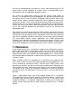
Section 1: Introduction / Definition 1.1 Executive Summary Electrical Engineering is a diverse field with applications that affect everyone in the world on a daily basis. Currently, one of the most vitally relevant and important topics is the practical use and application of energy efficient devices. An area in need of improvement is heating, cooling, and ventilation systems.
unit can be commanded by the finger or a stylus. When purchasing the LCD touch screen it will be composed of a touch sensor, a microcontroller, and a software driver with the appropriate operating system. Our system will communicate wirelessly with the internet using routers to connect. . An integrated circuit chip embedded in the printed circuit board inside the control unit will send and receive information from the router back to the control system. Ideally, we would employ the 802.
Figure 1 Residential Energy Use (Permission Pending from National Academy of Sciences) As the cost of energy increases, the need for a low power, energy efficient HVAC system becomes a more prominent concern. An intelligent HVAC control and monitoring system would allow the user to track their energy costs throughout the month and the year. Month to month cost tracking will allow the user to determine their optimal climate settings based on how much they are willing to spend on electric.
for the user. A smart HVAC control system would have a diagnostic element that would present the user with the expected problem and a solution for the problem. Remote control of the HVAC system is another motivation behind a smart control system. Since such a large percentage of the population have internet ready mobile devices in their pocket whenever they are on the go, there is a need to allow these people to control their HVAC systems while away from the building it is installed in.
determine whether or not the outdoor air is suitable to be brought into the building. Another objective of the remote sensing unit is to be easily installed. The remote sensing unit is to be battery powered and report all information to the main control unit wirelessly. By specifying these two characteristics the person installing the unit has the difficulty of their job greatly decreased.
1.3.3 LCD Touch Screen Display The objective of the LCD touch screen display is to provide the user an intuitive, easy to manipulate means of controlling the system. The display should be large in size so that it is easy to see when mounted on a wall. The buttons should be of ample size so that they are easily manipulated with a normal sized finger. The display should be color, and look professional.
The system is intended to be able to be retrofitted to an existing HVAC system, and therefore several requirements must be taken into consideration. In order to avoid running wire inside an existing structure, the temperature and relative humidity measurements are required to be transmitted to the main control unit wirelessly.
The system needs to be able to expand for features to be added in the future. Later on the sponsors may want to develop another version of the system with an expanded feature list. The microcontroller is required to have extra memory available to add these features.
programmer. He is also the only group member with experience in setting up a web server therefore he is best fit for that responsibility as well. The web server is an extremely important part of the project because it is what allows the LCD control panel to be viewed and manipulated remotely from a mobile device. Our sponsors have repeatedly informed us that this is one of the most important application features of all the requirements they have given our group.
Roles and Responsibilities for Senior Design I Paper Derick Executive Summary Motivation Objectives Research Methods Relays Sensors Dampers Design Architecture Thermostat Cory Detailed Specifications Detailed Requirements Touch Display Smart Phone Microcontroller Main Control Unit Andrew Block Diagrams Timelines Wireless Interfacing Actuators Schematic Layout Joshua Project Budgeting and Financing Goals Scripting Power Supply -Batteries -AC/DC Indoor and Outdoor Sensors Section 1: Definitio
microcontroller has multiple inputs (user settings, indoor temperature and relative humidity conditions, and outdoor temperature and relative humidity conditions) that it must accept as input. We are required to create a program to load onto the main microcontroller that will take these inputs into account and will control the appliances associated with the HVAC system. The LCD controller is the other component that requires programming.
will allow us to write the code in the C language which we are all familiar with. This part of the programming determines how the building will be cooled or heated so we plan on confirming all of the logic with our sponsor prior to starting to code everything into C. This coding is probably the most important coding aspect because it determines if the system functions properly.
Efficient HVAC Control and Feedback System User Interface Remote Sensing Unit Bidirectional communication with Main Control Unit Touch screen interfacing allows user to manipulate interface with his/her finger 7 inch display allows for visually appealing and easy to use display Precision measurements of temperature and relative humidity Wireless communication with main control unit to report data Weatherproof housing Battery powered for ease of installation Main Control Unit B
Our project was selected during the first meeting with Dr. Richie when he reviewed our “iTemp” project idea and asked us if we would like to accept a project that had been brought to his attention by AC3 Development Group, LLC. After the meeting with Dr. Richie, we decided to set up milestones for our group. The milestones would help us in several ways. They would allow us to better “divide and conquer” the paper, rather than looking at it as one huge assignment.
cited and the necessary steps have been taken to avoid copyright infringement, and to get the document printed, bound, and ready to hand in. Figure 4 Milestone Timeline Figure 5 pictured below is another timeline. This timeline describes the meetings that have been set up to discuss the project. The most common of these meetings is between the members of the group. The group on average meets three times per week in the Harris Engineering Building. Group meetings are informal and typically last 1-2 hours.
Figure 5 Meeting Timeline The other type of event in Figure 5 above is sponsor meetings. These do not have a set schedule, but happen when the group decides that they need to meet with the sponsors face to face because email communication is not sufficient. These meetings are slightly more formal in that the group reserves a specific meeting room in the Harris Engineering Building, but casual attire is still acceptable.
The sponsor will order all of the parts and have them shipped to their place of residence. In order to provide the sponsor with the list of parts to be ordered, we will create an account at the website of the manufacturer of the parts. The group will then select which parts are to be purchased, place them in an online “shopping cart” and provide the sponsor the Username and Password so that the shopping cart can be accessed.
Section 2: Research 2.1 Research Methods Our group came together and met generally for 2 days every week and would distribute and assign the various components to the Senior Design project for each group member to do individual research on. For every meeting we had devised how we would tackle individual tasks in accomplishing our main goal in building the Efficient HVAC Control and Feedback System. Everyone made suggestions and posed relevant questions to our sponsors by email.
For the design section of the report we focused our research on the specific parts we chose for the Efficient HVAC Control and Feedback System. Each part came with either a datasheet or a user manual (sometimes both) provided by the vendor selling the product. These datasheets and user manuals were essential because they provided us with the detailed information that was necessary to explain our subsystem in the design section of the research paper.
microcontroller to ensure we develop the main microcontroller to operate to their exact specifications. The performance of the main microcontroller is truly a “make or break” aspect of the Efficient HVAC Control and Feedback System that we are developing. The section below describes the research conducted to find the most appropriate microcontroller for the given set of requirements.
main microcontroller to communicate with the other components of the main control unit. In addition to these components, the main microcontroller is required to connect to relays to control the other components of the HVAC system such as compressors, air handlers, and a dehumidifier. Our sponsors have specified that they would like 20 I/O ports available specifically for controlling relays associated with components of the HVAC system. That specification brings our total needed pin count to 33 I/O ports.
The MPLAB Integrated Development Environment and the MPLAB C30 C Compiler are ideal for our project because it allows us to program the microcontroller in the C language. The C language is a high level language which makes programming the microcontroller much easier. The C language is the language that we are most familiar with as a group, and therefore this is ideal for our programming needs.
from the same manufacturer we are able to use the same development board to program multiple devices. Voltage and current requirements: The source voltage driving our main control unit is assumed to be 24V AC. This assumption has been made based on the fact that the main control unit will be installed where there was previously a thermostat mounted or installed in a new HVAC system as the main thermostat.
understandable form that the user will be able to comprehend. The microcontroller has 256 Kbytes Flash Memory which will hold our programming and allow the program to be modified in the future should more features be added to the system. The 30 Kbytes RAM on the chip should allow the system to run sufficiently fast.
The I2C protocol will be used to interface the main microcontroller to the temperature and relative humidity sensor. The microcontroller can support up to two I2C modules at one time. This leaves one I2C port available should another component be added in the future that requires an I2C connection. I2C: 2 modules supported Full Multi-Master Slave mode support 7 and 10 bit addressing The UART protocol will be set up to be our serial connection to the LCD display.
the dsPIC33FJ256GP710A. The cost of the microcontroller itself is a very small percentage of our overall costs, but we kept in mind that should this system be mass produced, even the cheapest of components amounts to a significant amount of money and therefore cost should be considered for ever component. During development, we must stay within the specified Absolute Maximum Electrical values.
Pin Name Pin Type Pin Description AVDD Power Positive supply for analog modules. AVSS Power Ground reference for analog modules VDD Power Positive supply for peripheral logic and I/O pins VSS Power Ground reference for logic and I/O pins VCAP/VDDCORE Power CPU logic filter capacitor connection MCLR Input/Power Master Clear (Reset) input. This pin is an active low reset.
The main microcontroller shares the main control unit with two devices requiring SPI connections, one device requiring an I2C connection, and one device requiring a UART connection.
output rating. This component is not included in the following diagram, but will be discussed in detail in the relays section of this paper. Figure 8 shows the interfacing within the main control unit. It also specifies the type of connection used and the number of wires required for each connection type. Main Control Unit Interfacing Figure 8 Main Control Unit interfacing The dsPIC33FJ256GP710A can connect to 2 UART, 2 I 2C, and 2 SPI modules. As the diagram shows, both the ZigBee and the 802.
2.3 Secondary Microcontroller For the secondary microcontroller for the system, we needed a simple and very low power consuming component. This secondary microcontroller will be battery powered as connecting to a permanent power source is not the end goal for the system. The secondary microcontroller will interface with the sensors and 802.15.4 ZigBee wireless chip. We have chosen to use the PIC24F04KA201, 20 Pin general purpose 16 Bit flash microcontrollers manufactured by Microchip®. 2.3.
4 Kbytes Flash Program Memory for storing and executing application code 512 Bytes RAM data memory The microcontroller is also capable of up to 16 MIPS (Millions of Instructions Per Second), which is standard for a microcontroller of this size and power. The microcontroller is optimized to be programmed in the C language, the preferred programming language of the group. The secondary microcontroller will be responsible for taking in the data from the SHT21 sensor.
Secondary Microcontroller I2C Interface SPI Interface MRF24J40MB PIC24F04KA201 ZigBee Wireless Transceiver Secondary Microcontroller SHT21 Temperature and Relative Humidity Sensor Power Battery Ground Figure 9 Secondary Microcontroller Interfacing 2.4 Relays Heating, Cooling, and Air Circulation is accomplished with the help of relays that act as switches to turn on and off these systems. The relays are triggered by digital logic as a result of readings from temperature and humidity sensors.
Some important factors when choosing the best relay to purchase for the HVAC control system are: Affordability, whether it is cost efficient for your budget in designing an HVAC system Contact configuration: Single Pole Single Throw, Single Pole Double Throw, Double Pole Double Throw, Three Pole Single Throw, Four Pole Single Throw, or Four Pole Double Throw Coil voltage, how much voltage do you want the coils of the relay to operate at from the available supply source in order for it to
Figure 10 Typical HVAC relay setup Researching different types of relays led us to come across the website: http://www.deltrol-controls.com/. This website is pretty good because deltrolcontrol is a leader in the design and manufacturing of electronic components. They also have very detailed and well explained part specification sheets that list what type of relays are used for certain applications. The relay that our group is interested in is the 263/268 series relay.
the relay receives the correct current and voltage. Another option for this step is to use a relay driver which is a surface mount chip with several transistor circuits inside. The advantage of this type of device is that the design is simplified because the designer does not have to implement multiple complex circuits into the design of the printed circuit board. This will be discussed further in the Relay subsection of the Design portion of this paper. 2.
The surface acoustic wave technology features two transducers so that when the panel is touched it can find the coordinate accordingly. These transducers are positioned on the x and y axes of the coordinate plane of the screen‟s insulated plate. The controller calculates the time at which the height of the acoustic wave falls to determine the x and y coordinates position on the x-y coordinate plane. This technology can also figure out how much pressure is applied to by the screen.
Continuous imaging of touch profile Image processing controller Image of changes in electrostatic field caused by touch Touch screen (sensor) Coordinates feed back to operating system Controller resolves touch profile to actual touch point Figure 13 Capacitive touch screen (Reprinting Permission Requested from 3M Touch) To differentiate all three different varieties of touch screens, the resistive touch technology is the cheapest to purchase on the market whereas its graphics and quality are the worst
last?) 5 years for 5 Wire Cost Inexpensive Expensive Average cost Sensitivity Very sensitive to scratch Sensitive to scratch Sensitive to dirt Advantages Inexpensive, can detect any object, not sensitive to water, humidity or dust Can be used on curved surface, not sensitive to water Average cost, scratch resistant, not sensitive to humidity or temperature Disadvantages Sensitive to scratch, low fidelity, and reduce visibility of the touch screen Very expensive, sensitive to scratch Can onl
driver will permit the touch screen and the computer to work together. The most commonly used touch screen driver is the mouse-emulation type driver which functions the same way as clicking the mouse at the same place on the screen. The touch screen can coexist together with existing software and will permit new technological applications to occur without the need for programming.
2.6.1 Ethernet and Wireless Routers Ethernet is a branch of wired technologies under the Local Area Network communication. Ethernet‟s standard practice used is the 802.3 which has been created since the 1980‟s. Changes have occurred in the recent years to make the Ethernet have higher bandwidth quality and improved media access control methods. The standard connector used to connect the Ethernet port from the computer to the Ethernet jack in the wall is called the RJ45 connector.
relays controlling the different heating and cooling options so that the appropriate action can be carried out. The question becomes which form of wireless technology will be most effective for caring out these decisions and actions. With so many different choices of wireless communication, certain key features must be accounted for and analyzed before we can select the best option.
Pros Cons Transmission range between 10 – 75 meters (33 -264 feet) and up to 1500 meters for ZigBee pro On the cluttered 2.
transmit approximately 10m and Class 3 uses up to 1mW of power and can transmit approximately 1m. Like any protocol, there are drawbacks and problems with Bluetooth. Bluetooth has problems with wall penetration, which is a major concern for our system. Bluetooth also uses more power for the distance the data is traveling compared to ZigBee. Another drawback is that other house appliances, like wireless home telephone, ZigBee and Wi-Fi signals clutter the 2.4 GHz ISM band.
(Mbps), which is overkill for our system. By adjusting throughput to 1 Mbps, we can extend the indoor range from 30 meters, to 90 meters, which is again more than enough for our system. Additionally, Wi-Fi® has many security measures in place, such as Wi-Fi Protected Access (WPA, WPA2) and Wired Equivalent Privacy (WEP) encryptions to protect the wireless networks security. After analyzing the capabilities of IEEE 802.
the main microcontroller through the ZigBee method, it too must have some basic requirements, which are also listed below in Table 9.
This means there is a huge market for applications to allow consumers to access and manipulate their home or office appliances and HVAC systems while away from the building. This also ensures optimum settings to save energy and money when the user is away from the building. Below is a discussion on how such a system would be implemented in order to provide remote access. 2.7.2 TCP/IP The Internet Protocol Suite, or TCP/IP, is a set of communication protocols used for the Internet.
2.7.4 Internet Layer The Internet layer helps define how interconnected networks function. This layer is the lowest layer concerned with devices that are located on a remote network, where as the Host-to-Network layer was only concerned about locally connected devices. In order to communicate with remote networks, the Internet layer provides logical addressing via Internet Protocol (IP).
2.7.6 Application Layer The application layer is that which network applications operate at. Applications that operate at this layer are, for example, HTTP, FTP, SMTP, DHCP, NFS, Telnet, SNMP, POP3, NNTP and IRC. The function of this layer is that it provides services to programs that want to use the network and to issue the appropriate commands to properly use the services provided by the lower levels. 2.7.
TCP/IP Stack uses a multitasking technique called cooperative multitasking. In a cooperative multitasking system, there is more than one task; each performs its job and returns its control so that the next task can perform its job. StackTask and ARPTask are cooperative tasks. Normally cooperative multitasking is implemented in the operating system or in the main application, but with Microchip‟s design, it is independent of any operating system; it implements its own cooperative multitasking system.
MPFS_WRITE_PAGE_SIZ E(mpfs.h) 1-255 To define writable page size for current MPFS storage media Table 11 Configuration used by MPFS.C StackTsk.c manages the operations of the stack and its modules. Which modules you enable are defined within the configurable defines. The values related to StackTsk.c are provided in Table 12 below.
not required. This module will be automatically enabled if there is at least one high-level module requiring TCP. Table 13 Configuration used by TCP.c User Applications have access to default network setting values as well as access to actual network setting values. Default values are defined within the configuration, whereas the actual values are saved by applications that are currently running. Below is Table 14 which provides a list of definitions and the values they can be.
UDP applications Table 15 Configuration used by UDP.c MAC.c handles the Media Access Control operations. This allows for the emulation of a full-duplex logical communication in a multi-point network. In Table 16 below are the configuration defines that MAC.c uses. Define Values Purpose To define individual transmit MAX_TX_BUFFER_SIZE 201-1500 buffer size To define total number of MAX_TX_BUFFER_COUN transmit buffers. This number is 1-255 T limited by available MAC buffer size.
To define maximum number of 1-31 HTML form fields including HTML form name MAX_HTML_CMD_LEN To define maximum length of 1-128 (HTTP.c) HTML form URL string. Table 18 Configuration used by HTTP.c MAX_HTTP_ARGS (HTTP.c) FTP.c implements a simple File Transfer Protocol application. The purpose of this is to allow an easy way to upload MPFS image files to the host device. Table 19 below shows the configurable values used by the FTP server.
// Declare this file as main application file #define THIS_IS_STACK_APPLICATION #include “StackTsk.h” #include “Tick.h” #include “dhcp.h” // Only if DHCP is used. #include “http.h” // Only if HTTP is used. #include “ftp.h” // Only if FTP is used. // Other application specific include files ... // Main entry point void main(void) { // Perform application specific initialization ... // Initialize Stack components. // If StackApplication is used, initialize it too.
that the same message can be retransmitted, if required. The size of this buffer can be specified. 2.7.9 Microchip HTTP Server With Microchip‟s TCP/IP Stack comes a minimally implemented HTTP server. The overburdened HTTP is stripped down to the essential features. The end user is left to code their own features if more is needed. The HTTP server incorporates a set of useful features to the user.
Figure 17 Uploading an MPFS Image using FTP To provide the user with a dynamic page in order to view current system data, the use of CGI will be needed. With the Microchip HTTP server, the HTTP GET option is already implemented. When the HTTP server encounters a string „%xx‟ in a CGI page that it is serving, it calls the function HTTPGetVar. The function is implemented by the main user application and is used to transfer application specific variable status to HTTP.
Possible values for this parameter are: Value HTTP_START_OF_VAR Meaning This is the very first callback for given variable for the current instance. If a multi-byte data transfer is required, this value should be used to conditionally initialize index to the multi-byte array that will be transferred for current variable Main application specific value. For all others val [out] One byte of data that is to be transferred Return Values New reference value as determined by main application.
During processing of this file, HTTP encounters the „%04‟ string. After parsing it, HTTP makes a callback. HTTPGetVar(4, HTTP_START_OF_VAR, &value). In Figure 20, the main user application implements HTTPGetVar function as follows: WORD HTTPGetVar(BYTE var, WORD ref, BYTE *val) { // Identify variable. // Is it RB5 ? if ( var == 4 ) { // We will simply return „1‟ if RB5 is high, // or „0‟ if low. if ( PORTBbits.RB5 ) *val = „1‟; else *val = „0; // Tell HTTP that this is last byte of // variable value.
Figure 21 MPFS Image Format The length of the Reserved Block is defined by MPFS_RESERVE_BLOCK. This block can be used by the main application to store simple configuration values. The storage begins with one or more MPFS FAT entries, followed by one or more file data. The FAT entry describes the file name, location and its status. Figure 22 below describes the format for the FAT entry. Figure 22 MPFS Fat Entry Format The Flag indicates whether the current entry is in use, deleted, or at the end of the FAT.
block. All file names are stored in upper case to make file name comparisons easier. Each FAT entry points turn to a data block that contains the actual file data. The data block format is shown below. The block is terminated with a special 8-bit flag called EOF (End of File. Followed by FFFFh (for 16-bit), or FFFFFFh (24-bit addressing). If the data portion of the block contains an EOF character, it is stuffed with the special escape character, DLE. Any occurrence of DLE itself is also stuffed with DLE.
2.11 Scripting Languages 2.11.1 PHP PHP is a widely used, general-purpose scripting language. It was originally designed for web development to produce dynamic web pages. To accomplish this, PHP code is embedded into the HTML source document and interpreted by a web server with a PHP processor module, which then would generate the web content. The code is executed at runtime to generate the dynamic information.
2.12 Power 2.12.1 Main Control Unit / LCD Touch Screen User Interface The main control unit and LCD touch screen user interface are to be a replacement unit for the existing HVAC control system thermostat or the main thermostat in the control system. In HVAC systems, the thermostat is usually powered by a 24V AC wire that is installed when the building is initially built and therefore 24V AC is what will be used to power our main control unit and LCD touch screen user interface.
2.13 Batteries Batteries are going to be used to store capacitive charge in the secondary microcontroller for the HVAC control system. The two kinds of batteries that exist today are primary batteries and secondary batteries. For our project we will most likely use the secondary batteries which are also known as rechargeable batteries. This is good because once the microcontroller runs out of battery life it can be recharged up as many times as we want.
These batteries on average contain a voltage of 1.2 V, a specific energy of approximately 70 W*h/kg, and an energy density of 300 W*h/L. Lithium-ion batteries are most commonly used in consumer electronics such as portable laptops, mobile cell phones, calculators, thermometers and many other devices. These batteries carry out a nominal value in voltage from 3.6 to 3.7 V. Also out of all the other available rechargeable batteries, these are the most powerful as well as the most expensive in cost.
electricity mains. A brownout occurs when there is a decrease in voltage from an electrical power supply. Both of these conditions have serious causes for public health, safety, the economy, and the environment. The next topic is climate change and smog which air conditioning is a primary contributor for. Air conditioners are one of the leading causes in climate change around the world.
When using the manual air control timer mode: Door 1 (damper 1) is open, door 2 (damper 2) is closed and door 3 (damper 3) is open. When using the automatic energy-save mode: If the system calls for central air conditioning and the outside air meets conditions then door 1 (damper 1) is open, door 2 (damper 2) is closed and door 3 (damper 3) is open.
handle on the outside of a duct. Depicted below in Figure 25 is an example of what manual balancing damper looks like. 18" 18" Figure 25 Manual balancing damper (Reprinting Permission Requested from Gran-Stratman Industries Inc.) Figure 26 pictured below shows a volume control damper also known as an automated zone damper. Notice these differences in operations from these two dampers. 18" 24" 18" 12" Figure 26 Volume control damper (Reprinting Permission Requested from Gran-Stratman Industries Inc.
In order to purchase HVAC automated zone dampers there are some questions that must be considered before a purchase is made. Pick an accurate size in diameter for the damper that you will need. Some dampers come in lengths of 6 inches and 8 inches. Also determine the automated zone damper variety that you want, either normally open or normally closed. Subsequently you need to figure out how many dampers you will need and also make sure to purchase a 24 V AC power supply and electrical wire.
commercial units, vehicles as a digital or analog display, and thermometers (to read a person‟s internal temperature or for instance; to read the temperature of a swimming pool). These sensors are linearly proportional because as the temperature changes the resistance changes as well. The different varieties of temperature sensors are resistance temperature detector, thermistor, and a thermocouple.
2" Figure 28 Bead type thermistor ((Permission is granted under the GNU Free Documentation License, http://en.wikipedia.org/) Different temperature sensors have a wide range of temperatures pre-designed within each IC chip for manufacturing and functionality purposes. In Florida, we would generally want a temperature sensor to have a range of temperatures from 40 or 50 degrees F to probably 90 degrees F.
efficient or cost - effective the sensor is. If all these conditions are met, then the customer is on the right track in purchasing a sensor. Another most commonly used sensor is the humidity sensor. In most electronic control systems, there are three different varieties of humidity sensors: the Dunmore element, Pope Cell, and finally the Polymer sensor.
Figure 30 Output Signal in mV vs. Absolute Humidity in g/M3 for Thermal Conductivity sensors (Reprinting Permission Requested from Questex Media Group LLC) Another name for the Polymer sensor is a Capacitive Humidity sensor. These sensors calculate the change in the electrical impedance using an ammonium salt substrate. The resistance of a humidity sensor is directly proportional according to its relative humidity.
whether the sensor is weather proof or resistant, cost - effectiveness, size, and maintainability. Relative humidity is an important concept especially in the state of Florida because in the summer season it is extremely hot and humid above what the actual temperature outside is supposed to be. Sometimes when the actual temperature is 96 degrees F, the relative humidity (for example; 100% humidity) causes the temperature to feel like it is 102 degrees F outside.
where Tc = temperature in degrees Celsius. The vapor pressure of the air is also found according to the following equation: where Tdc = dew point temperature in degrees Celsius. Absolute humidity is declared as the mass of water vapor that is contained in per unit volume of space. The formula is: where mw = mass of water vapor, and Vnet = total moisture of air (in m3). Each measurement variable previously explained all represent the same water vapor in air condition. Section 3: Design 3.
Main Control System Wireless Sensor «uses» Get Sensor Readings Process HVAC Control Humidifier «uses» Power Relays Adjust Settings AC1 «extends» «extends» AC2 Adjust Venting System User Adjust Power Settings Adjust Comfort Settings Venting Figure 32 Use Case Diagram for MCU For the wireless sensor, the software design is more basic. The main control unit will transmit a request for information. When this operation is received, the system will gather the current sensor reading.
Key Features of the MRF24J40MB Operates on ISM Band 2.405 – 2.475 Small size: 22.9 mm x 33.0 mm GHz freq. Supports ZigBee®, MiWi and MiWi Surface mountable P2p wireless protocols Integrated PCB antenna Up to 4000 ft. Range Operating voltage 2.4V – 3.6 V (3.3V typical) Low current consumption Table 22 Features of MRF24J40MB The MRF24J40MB module is compatible with Microchip‟s ® Microcontroller Families (Pic16F, PIC18F, PIC24F/H, dsPIC33).
clock (SCK), while the data will exchange through the SPI data in and out (SDI, SDO) pins. All data communications with the module are through the SPI interface. Figure 35 MRF24J40MB to Microcontroller Interface (Reprinted with permission from MicroChip®) When operating the MRF24J40MB RF transceiver module, supplying power to the chip is one of our biggest challenges. Making sure that the voltage to the different parts on the chip is correct is essential.
Digital I/O Input High 0.5 x VDD ______ VDD + 0.3 V Voltage (VIH) Input Low -0.3 ______ 0.22 x VDD V Voltage (VIL) Table 23 MRF24J40MB Recommended Operating Conditions (Reprinted with permission from MicroChip®) One of the great features of the MRF24J40MB is the low current consumption that allows the RF transceiver module to ultimately consume less power. The module has three modes: Sleep, Transmit (TX), and Receive (RX).
The main block diagram for the MRF24WB0MA module is shown in Figure 36 below. This diagram depicts the main connections between the different components within the RF transceiver module. The arrows on the right show how it will connect with the microcontroller.
The MRF24WB0MA has several power states. These are Hibernate, Sleep, and Active, which has two sub-states. The power state diagram in table 24 below show how the 3.3V power (VDD) is supplied during the different states of MRF24WB0MA. The overall power consumption of the system depends on which state is referenced during operation. State VDD Description Off 0V 0V Hibernate 3.3V 3.3V Sleep 3.3V 0V RX On 3.3V 0V TX On 3.3V 0V Standby 3.
Figure 38 MRF24WB0MA Power State diagram (Reprinted with permission from MicroChip®) 3.3 Temperature and Relative Humidity Sensor In order to measure temperature and relative humidity, we have chosen to implement the SHT21 temperature / relative humidity sensor made by Sensirion. This was chosen because it measures both the temperature and humidity, thus simplifying our design by eliminating the necessity for two sensors.
Figure 39 SHT21 Normal operating range (Reprinted with permission from Sensirion) The SHT21 has a default resolution of 12 bits for relative humidity and 14 bits for temperature. At this resolution, with a VDD of 3.0V and at 25˚C, the sensor has accuracy for relative humidity and temperature of +-2.0%RH and +-0.3˚C respectively.
Data can be transmitted across the SDA line only after a “start condition” has been met. The start condition entails the SDA line going from high to low while the SCL is high. Once data transmission is complete, a “stop condition” of the SDA going from low to high while SCL is high. Once the start condition has been acknowledged, the data bits are set while SCL is low (blue sections) and the data is transmitted and received while the SCL is high (green sections).
sensor without having to turn off the power. The soft reset function takes less than 15ms. The user register is an eight bit register that comes from the factory with default settings. It initially sets the resolution of relative humidity to 12 bits and temperature to 14 bits. The default register settings are shown in Figure 43.
TFT-LCD panel, and the SLCD5 controller (SLCD5 controller will be discussed in detail in a later section). To activate the LCD touch screen we can either use the user‟s finger or a pen to input various states for our HVAC control system.
3.4.1 Environmental Conditions for Evervision LCD Panel Our resistive touch screen device we purchased has many environmental conditions to consider. They include storage temperature and operating ambient temperature. Storage temperature has a min value of -30º Celsius and a max value of 80º Celsius. For the operating ambient temperature parameter it functions by having a min value of -20º Celsius and a max value of 70º Celsius.
3.5 SLCD5 Controller The SLCD5 controller is what provides the GUI for the LCD interface. It is meant to give the developer a simple way to generate a user interface on the screen to fit his or her needs without having to do a lot of low level graphical programming. The controller board is essentially the connector piece between the microcontroller and the LCD interface. The microcontroller would not be capable of producing the necessary images on the LCD screen as it does not have enough processing power.
Features of SLCD5 Drives digital TFT displays at QVGA Beeper for audible touch feedback and VGA resolution and alarms 16 bit color 3” by 4.5” size, 0.55” thick Touch controller (4 wire resistive) on High speed ARM9 proccessor board 200MHz On-board RS232 and TTL level 4MB data flash for user downloadable interfaces bitmaps with RLE compression Blacklight enable and brightness SD card slot for firmware upgrades control and bitmap / macro storage Table 29 SLCD5 features 3.5.
SLCD5. 4.5" 3.0" Figure 45 Connectors and Jumpers Layout of the SLCD5 (Reprinted with permission from Reach Technologies Inc) The SLCD5 can utilize either RS-232 or CMOS logic levels for serial communication. By default the COM0 serial port is configured for RS-232. The COM0 port is usually deemed the “Main” port and is connected to the embedded processor to control the display. The COM1 port is usually deemed the “Aux” port and is typically used to update the display bitmaps and macros.
3.5.2 Touch Interface The touch controller of the SLCD5 is meant to interface to a four wire resistive touchscreen. Touch sensitive areas on the display are defined as either “hotspots” or “buttons”. When either of these is pressed or released, the SLCD5 has the ability to either notify the host directly or execute a “macro” which is a predetermined sequence of SLCD5 commands. A hotspot is an area of the display that is touch-sensitive. The two types of hotspots are visible and invisible hotspots.
be in 24 bit RGB color. The SLCD5 uses 16 bit color in 565 formatting, but the BMPload program does the required translation. The BMPload program is designed to run on Windows XP. The computer that is running the BMPload program needs to be connected to the SLCD5 board using either the Main or Aux serial port. The first screen that appears when the BMPload program is booted allows the user to use an “Add BMP” button to add BMP files to the list.
state : Button number :Upper left hand corner of button : Button Type Button Define – Latching State Defines a touch button with two distinct states bd “text0” “text1” “text0”:String to be displayed on button state 0 “text1”:String to be displayed on button state 1 /: Text to be offset in x/y dir for “text0” /:Same as above for “text1” /:Index of bitmap in state 0/1 Define Hotspot (visible touch area)
allow a series of commands to be invoked by a single command. The two main advantages of this are to speed up the display and to reduce the space needed in the host processor to store the commands. Macros can have parameters associated with them so that a general purpose macro can be used in different ways on several screens.
#define example 1 t “‟0‟” „1‟ „2‟ #end The following command will use the above macro to display the text “Hello” at location x=40, y=50 >m 1 Hello 40 50 3.6 Design Summary The Efficient HVAC Control and Feedback System is composed of three major components. These components are the LCD Touch Screen User Interface, Remote Sensing Unit, and the Main Control Unit. Other design components being used in this project are the web server and the control and power relays.
Efficient HVAC Control and Feedback System User Interface Remote Sensing Unit Bidirectional communication with Main Control Unit Touch screen interfacing allows user to manipulate interface with his/her finger 7 inch display allows for visually appealing and easy to use display Precision measurements of temperature and relative humidity Wireless communication with main control unit to report data Weatherproof housing Battery powered for ease of installation Main Control Unit B
transmission. The ZigBee chip then transmits the information to the ZigBee chip on the Main Control Unit. The Main Control Unit is the most complex part of the Efficient HVAC Control and Feedback System. The Main Control Unit is composed of a main microcontroller, a ZigBee wireless transceiver, an 802.11b RF transceiver, control relays and a temperature and relative humidity sensor.
wireless chip. After considering readings from the sensors, the web server, and LCD user interface; the Main Control Unit must come to a decision as to what course of action to take. The Main Control Unit then controls the appropriate components of the HVAC system such as the compressors, air handlers, and dehumidifiers. The Main Control Unit is designed and programmed to use the least energy possible while satisfying the conditions set by the user.
shown below, illustrates the block diagram of the secondary microcontroller which contains the peripheral connection with the different components.
Figure 51 - Typical Relay setup for HVAC Control Systems The LCD touch screen user interface is one of two ways the user can interact with the system. The LCD touch screen user interface is mounted inside the building on the wall and is a replacement for a conventional thermostat. The LCD touch screen communicates with the main microcontroller through an attached controller board.
Section 4: Prototype 4.1 Vendors These vendors serve a special role and purpose in the development of the HVAC control system as well as have a direct association to our sponsors. All of these companies provided us essential components for our wireless microcontrollers, development board, LCD touch screen display, and wireless interfacing to communicate between the microchip and the router and vice versa.
4.1.3 Sensirion Sensirion is an engineering firm that is located in the municipality in the Canton of Zürich, Switzerland. This company consists of more than 180 employees that manufacturer sensor parts primarily for OEM applications. Sensirion was created in 1998 by Felix Mayer and Moritz Lechner. The products developed at Sensirion are applied in the medical field, automotive industry, and HVAC systems. The technology for the sensors integrates CMOS circuitry.
4) 5) 6) 7) 8) you give yourself enough workspace to add more electronic components if necessary. After that the PCB designer must select the number of layers that he wants for his design. The designer can choose from 2 layers, 4 layers, or 6 layers. 2 layers are mostly used for simple designs, 4 layers is preferably applied for medium-density designs, and 6 layers mainly works for high density or complex designs.
Pads are defined as a portion of a pattern on PCB‟s that are selected for the purpose of surface mounting electrical components. The important topics concerning pads involve their sizes, shapes, and dimensions. Pads heavily rely upon the manufacturing process used to make the printed circuit board as well as a person‟s solder ability. Another factor that is used to evaluate pads on a PCB is known as the pad or hole ratio. More generally the pad or hole ratio is referring to the pad size to hole size.
- - Another aspect about a snap grid is that it will make editing, movement of tracks, and components easier to do because the board will eventually expand in size. There are two types of grids in a PCB package that a developer in electronics can choose from: a visible grid or a snap grid. Design Equations for Printed Circuit Boards The first design factor for printed circuit boards to discuss about is the conductor capacitance.
Characteristic Impedance Zo = impedance of an infinitely long line (in ohms) R = resistance (in ohms) L = inductance (in H) G = conductivity per unit length of line (in mhos) C = capacitance (in F) A microstrip is an electric medium that can be made using a PCB. The cross sectional surface representation of a microstrip can be divided up into 4 components. These components are the conductor, the upper dielectric, dielectric substrate, and the ground plane.
main control unit was batteries but our group decided to implement the 24V AC wire into our design, saving the user the hassle of ever having to change batteries. In the future, a redesign may incorporate a backup battery system into the main control unit so that in the event that the building loses power, the backup batteries are able to power the system and the user‟s settings will not be lost. The main control unit houses several components of the overall design.
In order to transform the input voltage from 24V AC to 3.3V DC several steps must be taken. First, the signal needs to be converted from AC to DC. To accomplish this we have decided to use full wave rectification. This is also called bridge rectification and is accomplished through the implementation of four diodes. The bridge diode is an arrangement of four diodes in a diamond configuration so that no matter the polarity of the input, the polarity of output is the same no matter the polarity of the input.
signal, so a capacitor is placed between the rectifier and the regulator in order to further smooth the signal. Once smooth, the signal is now ready to be dropped to the necessary voltage by passing through a voltage regulator. This process is described in Figure 54 shown below. Figure 54 24V AC to 3.3V DC conversion 4.4 Remote Sensing Unit The remote sensing unit is designed to be mounted on the exterior of a building, where there will not be a power source available.
capable of providing current for an extended period of time. The secondary microcontroller draws 200mA max, the Zigbee chip draws 5mA max, and the temperature and relative humidity sensor draws 100mA max. The battery we have chosen is a 3.6V lithium battery to power the remote sensing unit. The nominal capacity of the battery is 2.1Ah which should be enough to power our unit for a sufficient amount of time.
SRS/SRSZ XX VDC S L Model of relay Nominal Coil Voltage Structure Coil sensitivity SRS 03 Sealed type L: 0.36W Table 34 Key Characteristics SRS - 03VDC - SL Relay For our system, we have decided to not connect the main microcontroller directly. Instead, we have chosen to implement a Darlington array driver. The Darlington array driver is basically multiple transistor circuits built into one chip.
delivered to the array driver when the I/O pin goes to its “high” state. This range of current is within the range accepted by the array driver to switch the corresponding internal transistor to the “on” state.
devices are subjected to. Figure 55 below shows an example of a possible weatherproof housing for the remote sensing unit. 5" 8" Figure 55 An example of a weatherproof wall mount housing for small electronic devices such as a remote sensing unit. (Permission to use photo pending) Since there will be a temperature and relative humidity sensor inside the weatherproof box we will need airflow into the box in order to get accurate temperature and relative humidity readings.
also be manipulating the temperature at the remote sensing unit to simulate the outdoor temperature. Depending on the temperature change at both locations along with user settings the system will come up with the correct course of action to maintain the user set points and take the appropriate course of action. We will set up several different scenarios to demonstrate the wide range of situations the system can handle.
5.1 Explorer 16 Development Board Microchip‟s® Explorer 16 Development board provides a low cost, modular development system for 16-bit microcontroller families. This board supports both the PIC24 and dsPIC33F microcontroller families which we will be using in the system. This will be the main testing device for our system. The Explorer Development board offers so many great features and capabilities that will be beneficial to our system for testing, prototyping and building.
Debugging and testing is going to be the Explorer 16 Development board‟s primary function. The 6-wire In-Circuit Debugger (ICD) connector included on the board connects to MPLAB ICD 3 software including in the development kit. The MPLAB ICD 3 is a programming/ debugging module made for beginning users for real time debugging, high speed programming and a ruggedized probe interface, perfect for protection against over voltage and current situations.
The MRF24J40MB PICtail/ PICtail Plus Daughter Board can be plugged into the Explorer 16 Development Board. The 30-pin card edge connector can be plugged into the PICtail Plus connector on the development board. Depending on if the card connects to the top section, or the mid-section of the board, it will connect to the SPI Port 1 and SPI Port 2 respectively, on the PIC® microcontroller plugged into the PIM socket, located at the center of the development board.
between the two devices, and the daughter board handles all of those connections as seen the Figure 59 below. Figure 59 MRF24WB0MA Signal Interface (Reprinted with permission from Microchip®) Once the PICtail daughter board in plugged into the Explorer development board, we will then have to download the correct Microchip® TCP/IP stack from Microchip‟s® Application Libraries at http://www.microchip.com/mal. The daughter board is compatible with the TCP/IP Stack version 5.25 or later.
5.5 Equipment To observe and test the behavior of our HVAC control system we are going to use the available devices that are presently in the Senior Design Lab. If some of the instruments are not there for us, we can always buy them from an independent vendor. Oscilloscope This device will allows us to view signal voltages on an x-y coordinate system. Even though the oscilloscope shows voltages on the y-axis any other quantity can be change to represent voltage such as current.
Soldering Gun This electric tool is used to solder loose wire connections in a circuit or network. To accompany the gun we must have solder thread to tap out or heat solder filament. 5.6 Environment The testing environment for the bulk of the time will be spent inside the Senior Design II lab. If other components that we purchase require more workspace to work then our group will go to selected off campus locations in order to construct our HVAC control system.
Main Microcontroller Secondary Microcontroller Supply Voltage: 3 – 3.6V Supply Voltage: 1.8 – 3.
intelligent decision to satisfy the preset temperature and relative humidity levels in the most effective and energy efficient manner. The system is intended to either be retrofitted to an existing HVAC system, or to be installed in a new building but only require essentially the normal wiring that would be installed for a normal HVAC system.
The subsystem that controls new air flow into the building is required to control four dampers in the ducts of the HVAC system, and is required to be controlled wirelessly. These four dampers will control airflow through the ducts depending on user controlled settings via the touch screen. If a dehumidification unit is not integrated into the existing HVAC system at the time the Efficient HVAC Control and Feedback System is installed, it must also be controlled wirelessly.
between the two settings allows the user to specify to the system how much the conditions must differ from the set conditions before action will be taken. This difference is known as the “comfort band.” The setting that has been selected will be shown to the user on an “energy usage bar” located on the home screen of the LCD display. In a standard 3-Ton air conditioning system, any time the inside conditions are not ideal the entire system is powered on, using about 4000 Watts of power.
component, the Main Control Unit. The Remote Sensing Unit uses a single sensor that is capable of making the temperature and the relative humidity reading. The sensor reports to the secondary microcontroller. The secondary microcontroller is the central component of the Remote Sensing Unit and is interfaced to the sensor and the wireless communication chip.
on the display and also reports to the main microcontroller what has been touched on the screen. The display is composed of a home screen and several sub screens. The home screen displays the logos of the sponsors, the current indoor conditions, the set points for temperature and relative humidity, the max comfort / max savings settings, and the energy usage bar. The software design process is another obstacle to overcome. The programming involves the “brains” of the system.
humidity as well as manipulate all other options that are available on the LCD touch screen. Considerations have been made to allow features to be added to the system in the future. All aspects of the system are able to be reprogrammed in the future. Features such as air purification components, CO2 sensors, airflow sensors, and severe weather alerts are all possibilities of additions to the system in the future.
Bibliography Levenhagen, John I. and Donald H. Spethmann. HVAC Controls and Systems. New York, NY: McGraw Hill, 1993. Heath, Steve. Embedded Systems Design. Oxford, UK: ButterworthHeinemann Ltd, 1997. Haines, Roger W. and Douglas C. Hittle. Control Systems for Heating, Ventilating, and Air Conditioning. New York, NY: Chapman and Hall, 1983. Wendes, Herb. HVAC Retrofits: Energy Savings Made Easy. Lilburn, GA: Fairmont Press, 1994. Bell Jr., Arthur A.
. Tennermann, Jim. The Chilled Mirror Dew Point Hygrometer as a Measurement Standard. Questex Media Group LLC, 2009. . Fisher, Jeff. HVAC Control Tutorial. HomeTech Solutions, 1992-2010.
“How Can I Get Started.” Getting Started with Embedded Touch Screens. Reach Technology Inc, 2010. . “All about Brushless Motors – What You Need to Know.” Brushless Motor Benefits. Dragonfly Innovations, Inc, 2008. . “Improved Academic Performance.” What Environmental Factors Are Important and Practical to Address?. U.S. EPA, April 12, 2010.
Appendix A: Datasheets Explorer 16 Development Board User‟s Guide by Microchip dsPIC33FJXXXGPX06A/X08A/X10A Data Sheet by Microchip PIC24F04KA201 Family Data Sheet by Microchip PIC24FXXKAXXX Flash Programming Specs MRF24WB0MA/MRF24WB0MB Datasheet by Microchip MRF24J40 Datasheet by Microchip SHT21 Datasheet by Sensirion SRS-03VDC-SL Datasheet by Songle Relay LM2937-3.
Appendix B: Copyright / Permissions Derick We would be glad to let you use 3M images with the proper "Provided courtesy of 3M Touch Systems" acknowledgement. Not all the images on that site were our images. Which ones are you specifically interested in? Regards, Tim. Tim Holt | Communications Manager 3M Touch Systems 3M Electro & Communications Business 501 Griffin Brook Park | Methuen, MA 01844 O: 978 659 9379 tholt@mmm.com | www.3M.com/touch Check out the new touch industry reference site: www.
service? Please complete the form below. Required fields are indicated by an asterisk (*). Top of Form *Subject of your message: Asking permission to use pictures on w ebsite Please provide the information that will help us respond to your request.
I am a Senior at the University of Central Florida in Orlando, Florida. I am in my Senior Design class and our group is building an HVAC control system. I w ould like to ask permissions to use the touch screen pictures on the w ebsite: http://w iki.fluidproject.org/display/fluid/Benchmarkin g+-+Touch+Screen+Options I w as told to contact you by the w ebpage publisher/author for permissions privileges.
National Semiconductor Permission: Evervision LCD Permission: 134
Reach Technology Permission: 135
Microchip Permssion: 136
Home > Contact Info Contact Us Your details will remain secure with us and will not be passed on to any third party. First Name * Derick Last Name * Holzmacher Title Electrical Engineer Densitron Europe Email sales@densitron.co.uk Phone: +44 (0)207 648 4200 Company * University of Central F Densitron America Email DCAWebSales@densitron.com Phone: +1 951-284-7600 x 252 You can also contact us at: Website Email * djho@tampabay.rr.co Densitron Asia Email sales@densitron.com.
Country * Postal Code/Zip * United States Or view our comprehensive offices and representatives section. 32765 * indicates a required field I am a Senior at the University o I am building an HVAC control s Comments Thanks very much. Contact Us Customer Care Elo takes all customer input seriously as part of our ongoing continuous improvement efforts. If we fail to meet your expectations, please let us know by submitting this form or calling 1-800-5571458 (option 2).
Phone 727-580-6767 Fax E-mail Address djho@tampabay.rr.com Sales Manager Action (Select one) Response Required Commentary Only Part Number (where applicable) Model/Description Serial Number(s) Describe Issue (max 3990 characters) Titled: Asking permission to use pictures on w e I am a Senior at the University of Central Florida http://w iki.fluidproject.
140
Abbreviations and Acronyms AC – Alternating Current ACK – Acknowledgement Frame ADC – Analog to Digital Converter CpE – Computer Engineering CPU – Central Processing Unit CR – Contrast Ratio EE – Electrical Engineering EEPROM – Electrically-Erasable Programmable Read-Only Memory GHz – Gigahertz GM – Group Meetings HVAC – Heating, Ventilation, and Air Conditioning I/O – Input/Output I2C – Inter – Integrated Circuit IC – Integrated Circuit / Integrated Chip IDE – Integrated Development Environment ISA – Indus