
Specifications


105
Characteristic Impedance
Z
o
= impedance of an infinitely long line (in ohms)
R = resistance (in ohms)
L = inductance (in H)
G = conductivity per unit length of line (in mhos)
C = capacitance (in F)
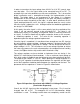
A microstrip is an electric medium that can be made using a PCB. The cross
sectional surface representation of a microstrip can be divided up into 4
components. These components are the conductor, the upper dielectric,
dielectric substrate, and the ground plane. Some drawbacks to the microstrip are
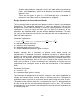
that they have minimal power handling capacity and high losses. Figure 52 is an
illustration of the linear geometric depiction of a microstrip being fabricated on a
PCB.
Figure 52 Microstrip Layout on a PCB
A is known as the top conductor, B is the upper dielectric medium, C is defined
as the dielectric substrate or level between the dielectric and the conductor, D is
referred to as the ground plane
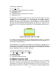
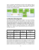
Illustrated below is the method to calculate the characteristic impedance of a
microstrip line. The impedance of the microstrip line is altered with the frequency
of the material being used. The quasi-static characteristic impedance can affect
how the frequency rises or falls for the substrate.
Characteristic Impedance for a Microstrip
h = dielectric thickness
W = microstrip width
E
r
= substrates dielectric constant
4.3 Main Control Unit
Our design calls for the main control unit to be powered by a 24V AC common
wire that is installed in the building during the initial construction project. The
advantage of this design is that the main control unit will run as long as there is
power being delivered to the building. The alternative method of powering the