
Specifications


106
main control unit was batteries but our group decided to implement the 24V AC
wire into our design, saving the user the hassle of ever having to change
batteries. In the future, a redesign may incorporate a backup battery system into
the main control unit so that in the event that the building loses power, the
backup batteries are able to power the system and the user‟s settings will not be
lost.
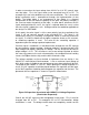
The main control unit houses several components of the overall design. The
components located in the main control unit are the SHT21 Sensor, the
dsPIC33FJ256GP710A main microcontroller, the Zigbee MRF24J40MB wireless
chip, and the MRF24WB0MA 802.11b wireless chip. Also associated with the
main control unit and therefore powered by the 24V AC wire will be the 7”
Evervision LCD touch screen and SLCD5 LCD controller. The 802.11b wireless
chip has an operating voltage range of 2.7V – 3.6V with a typical voltage of 3.3V,
the Zigbee chip has an operating voltage range of 2.4V -3.6V with a typical
voltage of 3.3V, the main microcontroller has an operating voltage range of 3V –
3.6V, and the LCD touch screen and SLCD5 controller require 5V – 12V, and the
temperature and relative humidity sensor has an operating voltage range of 2.1V
– 3.6V with a typical value of 3V. The SLCD5 controller has an on board
switching regulator that generates the 3.3V necessary for the panel to operate.
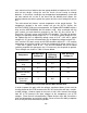
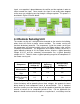
These voltages are shown in Table 32 shown below.
Component
Min Operating
Voltage (V)
Typical
Operating
Voltage (V)
Max Operating
Voltage (V)
Main
Microcontroller
3
N/A
3.6
Zigbee wireless
chip
2.4
3.3
3.6
802.11b wireless
chip
2.7
3.3
3.6
Temperature and
Relative Humidity
sensor
2.1
3
3.6
LCD Touch
Screen and
Controller
5
N/A
12
Table 32 Minimum, maximum, and typical operating voltages for
components associated with the Main Control Unit
In order to power the parts with the voltages mentioned above, there must be
circuitry placed on the PCB to convert the 24V AC leaving the wall into a smaller,
useable voltage. Another aspect of the circuit is that it must convert the voltage
from AC to DC because the input voltages to the components are all DC
voltages. Since the main microcontroller, Zigbee wireless chip, 802.11b wireless
chip, and temperature and relative humidity sensor all have the ability to operate
off 3.3V they will all be connected in parallel.