
Specifications
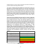

116
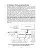
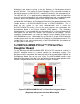
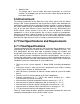
The MRF24J40MB PICtail/ PICtail Plus Daughter Board can be plugged into the
Explorer 16 Development Board. The 30-pin card edge connector can be
plugged into the PICtail Plus connector on the development board. Depending on
if the card connects to the top section, or the mid-section of the board, it will
connect to the SPI Port 1 and SPI Port 2 respectively, on the PIC®
microcontroller plugged into the PIM socket, located at the center of the
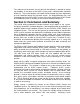
development board. Figure 58 below shows how the daughter board can be
easily implemented onto the development board.
Figure 58 MRF24J40MB PICtail™ Daughter Board plugged into Explorer 16
Development Board
(Reprinted with permission from Microchip®)
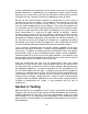
5.3 MRF24WB0MA Wi-Fi PICtail/ PICtail Plus
Daughter Board
To test Microchip‟s® MRF24WB0MA IEEE 802.11 Wi-Fi RF transceiver module,
a PICtail™ daughter board is a perfect solution for developing, testing. This
daughter board is compatible with Microchip‟s® 16-bit microcontroller Explorer 16
Development Board that we are also using. This demonstration board will
evaluate the Wi-Fi® connectivity of the microcontroller using the MRF24WB0MA
module.
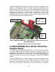
The MRF24WB0MA PICtail™ daughter board is very simple to program and to
use. The Input/ Output pins on the daughter board are very similar to the
connections on other Microchip products. The SPI Chip Select (CS), SPI clock
(SCK) and the SPI data in and out (SDI, SDO) are the basic 4 connections
MRF24J40MB
PICtail
Daughter Board
Explorer 16 Board
Plug-in
Module
(PIM)