
Specifications

62
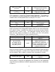
2.12 Power
2.12.1 Main Control Unit / LCD Touch Screen
User Interface
The main control unit and LCD touch screen user interface are to be a
replacement unit for the existing HVAC control system thermostat or the main
thermostat in the control system. In HVAC systems, the thermostat is usually
powered by a 24V AC wire that is installed when the building is initially built and
therefore 24V AC is what will be used to power our main control unit and LCD
touch screen user interface. 24V AC is ideal for this application because the
relays that are controlled by the main control unit are required to output 24V AC.
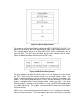
The relay outputs will essentially be tied to the input power by putting them in a
parallel configuration so that the voltage coming out of the wall in the building can
power the 220V AC relays at the units. The 24V AC outputted by the main
control unit can be thought of as “control voltages” because they are what is
delivered to the components (for example AC1 and AC2) of the system and will
control the power relays located at the units. The power relays are what control
the power needed to run the units (usually 220V/240V AC).
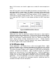
Within the main control unit there are several components that each needs to be
supplied with specific voltages. These components are the LCD touch screen,
the main microprocessor, the ZigBee wireless chip, the 802.11b wireless internet
chip, and the temperature and relative humidity sensor. Specifically, the LCD
touch screen requires 5 – 12V DC, the main microprocessor requires 3 – 3.6V
DC, the ZigBee wireless chip requires 3.3V DC, the 802.11b wireless Internet
chip requires 3.3V DC, and the temperature and relative humidity sensor requires
-0.3 to 5 V DC. To obtain these specific voltages, the printed circuit board must
be designed to deliver the proper amount of voltage to the corresponding
component using voltage regulators to ensure the correct voltage. Specifics on
the printed circuit board design are discussed further in the PCB Design section
of this paper.
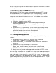
2.12.2 Remote Sensing Unit
The remote sensing unit will be powered by a single battery source. The remote
sensing unit is designed to be installed on the exterior of the building, and
therefore no existing power supply will be present. In order to keep installation
as simple as possible, and avoid running new wiring through an existing building,
the remote sensing unit will be battery powered. This means that in order to
install the remote sensing unit, it only needs to be secured to the building. The
remote sensing unit will be enclosed in weather proof housing, and the housing
will be one that is designed to be wall mounted. The details about using batteries
to power the remote sensing unit will be discussed further in the PCB Design
section of this paper.