
Specifications


75
User
Power Relays
Adjust Comfort
Settings
Adjust Venting
System
Adjust Settings
Adjust Power
Settings
«extends»
«extends»
Get Sensor Readings
Process HVAC
Control
«uses»
«uses»
Main Control System
Wireless Sensor
Humidifier
AC1
AC2
Venting
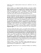
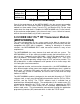
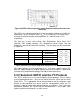
Figure 32 Use Case Diagram for MCU
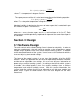
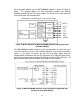
For the wireless sensor, the software design is more basic. The main control unit
will transmit a request for information. When this operation is received, the
system will gather the current sensor reading. This information is then
transmitted back to the MCU. Figure 33 illustrates the use case diagram for the
wireless sensor.
Get Sensor Reading Transmit Status
Wireless Sensor
Temp/RH Sensor
MCU
Figure 33 Use Case Diagram for the wireless sensor.
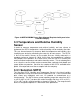
3.2 Wireless Communication
3.2.1 IEEE 802.15.4 2.4 GHz RF Transceiver
Module (MRF24J40MB)
The sensors and microcontrollers that are collecting the data need to be able to
communicate with the main microcontroller. We need a device with low power
consumption, low data rate, and secure networking which can accomplish this.
Microchip‟s® MRF24J40MB fit most of our requirements for a ZigBee device.
Some of the applicable features of the MRF24J40MB are listed below in Table
22.