
Datasheet


2016 Microchip Technology Inc. DS00002164B-page 19
LAN8710A/LAN8710AI
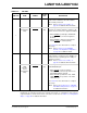
3.1.2 100BASE-TX RECEIVE
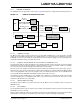
The 100BASE-TX receive data path is shown in Figure 3-2. Each major block is explained in the following subsections.
FIGURE 3-2: 100BASE-TX RECEIVE DATA PATH
MAC
A/D
Converter
MLT-3
Converter
NRZI
Converter
4B/5B
Decoder
Magnetics CAT-5RJ45
PLL
MII 25Mhz by 4 bits
or
RMII 50Mhz by 2 bits
RX_CLK
(for MII only)
25MHz by
5 bits
NRZI
MLT-3MLT-3 MLT-3
6 bit Data
Descrambler
and SIPO
125 Mbps Serial
DSP: Timing
recovery, Equalizer
and BLW Correction
MLT-3
MII/RMII
25MHz
by 4 bits
Ext Ref_CLK (for RMII only)
3.1.2.1 100M Receive Input
The MLT-3 from the cable is fed into the transceiver (on inputs RXP and RXN) via a 1:1 ratio transformer. The ADC
samples the incoming differential signal at a rate of 125M samples per second. Using a 64-level quanitizer, it generates
6 digital bits to represent each sample. The DSP adjusts the gain of the ADC according to the observed signal levels
such that the full dynamic range of the ADC can be used.
3.1.2.2 Equalizer, Baseline Wander Correction and Clock and Data Recovery
The 6 bits from the ADC are fed into the DSP block. The equalizer in the DSP section compensates for phase and ampli-
tude distortion caused by the physical channel consisting of magnetics, connectors, and CAT- 5 cable. The equalizer
can restore the signal for any good-quality CAT-5 cable between 1m and 150m.
If the DC content of the sig
nal is such that the low-frequency components fall below the low frequency pole of the iso-
lation transformer, then the droop characteristics of the tran
sformer will become significant and Baseline Wander (BLW)
on the received signal will result. To prevent corruption of the received data, the transceiver corrects for BLW and can
receive the ANSI X3.263-1995 FDDI TP-PMD defined “killer packet” with no bit errors.
The 100M PLL generates multiple phases of the
125MHz clock. A multiplexer, controlled by the timing unit of the DSP,
selects the optimum phase for sampling the data. This is used as the received recovered clock. This clock is used to
extract the serial data from the received signal.
3.1.2.3 NRZI and MLT-3 Decoding
The DSP generates the MLT-3 recovered levels that are fed to the MLT-3 converter. The MLT-3 is then converted to an
NRZI data stream.
3.1.2.4 Descrambling
The descrambler performs an inverse function to the scrambler in the transmitter and also performs the Serial In Parallel
Out (SIPO) conversion of the data.
During reception of IDLE (/I/) symbols. the descrambler
synchronizes its descrambler key to the incoming stream. Once
synchronization is achieved, the descrambler locks on this key and is able to descramble incoming data.