LAN8720A/LAN8720AI Small Footprint RMII 10/100 Ethernet Transceiver with HP Auto-MDIX Support Highlights Key Benefits • Single-Chip Ethernet Physical Layer Transceiver (PHY) • Comprehensive flexPWR® Technology - Flexible Power Management Architecture - LVCMOS Variable I/O voltage range: +1.6V to +3.6V - Integrated 1.2V regulator • HP Auto-MDIX support • Miniature 24-pin QFN/SQFN lead-free RoHS compliant packages (4 x 4mm). • High-Performance 10/100 Ethernet Transceiver - Compliant with IEEE802.3/802.
LAN8720A/LAN8720AI TO OUR VALUED CUSTOMERS It is our intention to provide our valued customers with the best documentation possible to ensure successful use of your Microchip products. To this end, we will continue to improve our publications to better suit your needs. Our publications will be refined and enhanced as new volumes and updates are introduced.
LAN8720A/LAN8720AI Table of Contents 1.0 Introduction ..................................................................................................................................................................................... 4 2.0 Pin Description and Configuration .................................................................................................................................................. 6 3.0 Functional Description ............................................................
LAN8720A/LAN8720AI 1.0 INTRODUCTION 1.1 General Terms and Conventions The following is list of the general terms used throughout this document: 1.2 BYTE 8-bits FIFO First In First Out buffer; often used for elasticity buffer MAC Media Access Controller RMII™ Reduced Media Independent InterfaceTM N/A Not Applicable X Indicates that a logic state is “don’t care” or undefined. RESERVED Refers to a reserved bit field or address.
LAN8720A/LAN8720AI FIGURE 1-1: SYSTEM BLOCK DIAGRAM 10/100 Ethernet MAC RMII LAN8720A/ LAN8720Ai Mode MDI Transformer RJ45 LED Crystal or Clock Oscillator FIGURE 1-2: MODE[0:2] nRST ARCHITECTURAL OVERVIEW Mode Control Reset Control AutoNegotiation 100M TX Logic 100M Transmitter HP Auto-MDIX RXP/RXN Transmitter RMIISEL SMI TXD[0:1] Management Control 10M TX Logic 10M Transmitter TXP/TXN MDIX Control TXEN XTAL1/CLKIN PLL XTAL2 RXER CRS_DV RMII Logic RXD[0:1] 100M RX Logic DS
LAN8720A/LAN8720AI 2.0 PIN DESCRIPTION AND CONFIGURATION FIGURE 2-1: 24-QFN/SQFN PIN ASSIGNMENTS (TOP VIEW) VDD1A 19 TXN 20 LAN8720A/LAN8720Ai 12 MDIO 11 CRS_DV/MODE2 10 RXER/PHYAD0 (TOP VIEW) TXP 21 RXN 22 9 VDDIO RXP 23 8 RXD0/MODE0 RBIAS 24 7 RXD1/MODE1 VSS NOTE: Exposed pad (VSS) on bottom of package must be connected to ground Note 2-1 When a lower case “n” is used at the beginning of the signal name, it indicates that the signal is active low.
LAN8720A/LAN8720AI TABLE 2-1: RMII SIGNALS Num Pins Name Symbol Buffer Type 1 Transmit Data 0 TXD0 VIS The MAC transmits data to the transceiver using this signal. 1 Transmit Data 1 TXD1 VIS The MAC transmits data to the transceiver using this signal. 1 Transmit Enable TXEN VIS (PD) Indicates that valid transmission data is present on TXD[1:0]. 1 Receive Data 0 RXD0 VO8 Bit 0 of the 2 data bits that are sent by the transceiver on the receive path.
LAN8720A/LAN8720AI TABLE 2-1: RMII SIGNALS (CONTINUED) Num Pins Name Symbol Buffer Type 1 Carrier Sense / Receive Data Valid CRS_DV VO8 Description This signal is asserted to indicate the receive medium is non-idle. When a 10BASE-T packet is received, CRS_DV is asserted, but RXD[1:0] is held low until the SFD byte (10101011) is received. Note: Per the RMII standard, transmitted data is not looped back onto the receive data pins in 10BASE-T half-duplex mode.
LAN8720A/LAN8720AI TABLE 2-2: NUM PINS LED PINS (CONTINUED) NAME SYMBOL BUFFER TYPE LED 2 LED2 O12 DESCRIPTION Link Speed LED Indication. This pin is driven active when the operating speed is 100Mbps. It is inactive when the operating speed is 10Mbps or during line isolation. Note: Refer to Section 3.8.1, "LEDs," on page 32 for additional LED information. 1 nINT/ REFCLKO Function Select Configuration Strap nINTSEL IS (PU) This configuration strap selects the mode of the nINT/REFCLKO pin.
LAN8720A/LAN8720AI TABLE 2-4: ETHERNET PINS (CONTINUED) Num PINs NAME SYMBOL BUFFER TYPE 1 Ethernet TX/ RX Positive Channel 2 RXP AIO Transmit/Receive Positive Channel 2 1 Ethernet TX/ RX Negative Channel 2 RXN AIO Transmit/Receive Negative Channel 2 TABLE 2-5: DESCRIPTION MISCELLANEOUS PINS Num PINs NAME SYMBOL BUFFER TYPE 1 External Crystal Input XTAL1 ICLK External crystal input External Clock Input CLKIN ICLK Single-ended clock oscillator input.
LAN8720A/LAN8720AI TABLE 2-6: ANALOG REFERENCE PINS Num PINs NAME SYMBOL BUFFER TYPE 1 External 1% Bias Resistor Input RBIAS AI DESCRIPTION This pin requires connection of a 12.1k ohm (1%) resistor to ground. Refer to the LAN8720A/LAN8720Ai reference schematic for connection information. Note: The nominal voltage is 1.2V and the resistor will dissipate approximately 1mW of power. TABLE 2-7: POWER PINS Num PINs NAME SYMBOL BUFFER TYPE 1 +1.6V to +3.6V Variable I/O Power VDDIO P +1.
LAN8720A/LAN8720AI TABLE 2-8: 24-QFN PACKAGE PIN ASSIGNMENTS Pin NUM Pin Name Pin NUM Pin Name 1 VDD2A 13 MDC 2 LED2/nINTSEL 14 nINT/REFCLKO 3 LED1/REGOFF 15 nRST 4 XTAL2 16 TXEN 5 XTAL1/CLKIN 17 TXD0 6 VDDCR 18 TXD1 7 RXD1/MODE1 19 VDD1A 8 RXD0/MODE0 20 TXN 9 VDDIO 21 TXP 10 RXER/PHYAD0 22 RXN 11 CRS_DV/MODE2 23 RXP 12 MDIO 24 RBIAS 2.
LAN8720A/LAN8720AI TABLE 2-9: BUFFER TYPES (CONTINUED) BUFFER TYPE OCLK P DESCRIPTION Crystal oscillator output pin Power pin Note 2-5 The digital signals are not 5V tolerant. Refer to Section 5.1, "Absolute Maximum Ratings*," on page 54 for additional buffer information. Note 2-6 Sink and source capabilities are dependent on the VDDIO voltage. Refer to Section 5.1, "Absolute Maximum Ratings*," on page 54 for additional information. 2016 Microchip Technology Inc.
LAN8720A/LAN8720AI 3.0 FUNCTIONAL DESCRIPTION This chapter provides functional descriptions of the various device features. These features have been categorized into the following sections: • • • • • • • • • Transceiver Auto-negotiation HP Auto-MDIX Support MAC Interface Serial Management Interface (SMI) Interrupt Management Configuration Straps Miscellaneous Functions Application Diagrams 3.1 3.1.1 Transceiver 100BASE-TX TRANSMIT The 100BASE-TX transmit data path is shown in Figure 3-1.
LAN8720A/LAN8720AI TABLE 3-1: 4B/5B CODE TABLE CODE GROUP SYM 11110 0 0 0000 DATA 0 0000 DATA 01001 1 1 0001 — 1 0001 — 10100 2 2 0010 — 2 0010 — 10101 3 3 0011 — 3 0011 — 01010 4 4 0100 — 4 0100 — 01011 5 5 0101 — 5 0101 — 01110 6 6 0110 — 6 0110 — 01111 7 7 0111 — 7 0111 — 10010 8 8 1000 — 8 1000 — 10011 9 9 1001 — 9 1001 — 10110 A A 1010 — A 1010 — 10111 B B 1011 — B 1011 — 11010 C C 1100 — C 1100 —
LAN8720A/LAN8720AI TABLE 3-1: 4B/5B CODE TABLE (CONTINUED) CODE GROUP SYM 00101 V INVALID, RXER if during RXDV INVALID 01000 V INVALID, RXER if during RXDV INVALID 01100 V INVALID, RXER if during RXDV INVALID 10000 V INVALID, RXER if during RXDV INVALID 3.1.1.3 RECEIVER INTERPRETATION TRANSMITTER INTERPRETATION Scrambling Repeated data patterns (especially the IDLE code-group) can have power spectral densities with large narrow-band peaks.
LAN8720A/LAN8720AI 3.1.2 100BASE-TX RECEIVE The 100BASE-TX receive data path is shown in Figure 3-2. Each major block is explained in the following subsections.
LAN8720A/LAN8720AI Special logic in the descrambler ensures synchronization with the remote transceiver by searching for IDLE symbols within a window of 4000 bytes (40us). This window ensures that a maximum packet size of 1514 bytes, allowed by the IEEE 802.3 standard, can be received with no interference. If no IDLE-symbols are detected within this time-period, receive operation is aborted and the descrambler re-starts the synchronization process. 3.1.2.
LAN8720A/LAN8720AI • • • • MII (digital) TX 10M (digital) 10M Transmitter (analog) 10M PLL (analog) 3.1.3.1 10M Transmit Data Across the RMII Interface The MAC controller drives the transmit data onto the TXD bus. TXD[1:0] shall transition synchronously with respect to REF_CLK. When TXEN is asserted, TXD[1:0] are accepted for transmission by the device. TXD[1:0] shall be “00” to indicate idle when TXEN is deasserted.
LAN8720A/LAN8720AI 3.1.4.4 Jabber Detection Jabber is a condition in which a station transmits for a period of time longer than the maximum permissible packet length, usually due to a fault condition, which results in holding the TXEN input for a long period. Special logic is used to detect the jabber state and abort the transmission to the line within 45ms. Once TXEN is deasserted, the logic resets the jabber condition. As shown in Section 4.2.
LAN8720A/LAN8720AI Once a capability match has been determined, the link code words are repeated with the acknowledge bit set. Any difference in the main content of the link code words at this time will cause auto-negotiation to re-start. Auto-negotiation will also re-start if not all of the required FLP bursts are received. The capabilities advertised during auto-negotiation by the transceiver are initially determined by the logic levels latched on the MODE[2:0] configuration straps after reset completes.
LAN8720A/LAN8720AI The internal logic of the device detects the TX and RX pins of the connecting device. Since the RX and TX line pairs are interchangeable, special PCB design considerations are needed to accommodate the symmetrical magnetics and termination of an Auto-MDIX design. The Auto-MDIX function can be disabled via the AMDIXCTRL bit in the Special Control/Status Indications Register. FIGURE 3-4: DIRECT CABLE CONNECTION VS.
LAN8720A/LAN8720AI 3.4.1.1 CRS_DV - Carrier Sense/Receive Data Valid The CRS_DV is asserted by the device when the receive medium is non-idle. CRS_DV is asserted asynchronously on detection of carrier due to the criteria relevant to the operating mode. In 10BASE-T mode when squelch is passed, or in 100BASE-X mode when 2 non-contiguous zeros in 10 bits are detected, the carrier is said to be detected.
LAN8720A/LAN8720AI FIGURE 3-6: MDIO TIMING AND FRAME STRUCTURE - WRITE CYCLE Write Cycle MDC MDIO 32 1's Preamble 0 1 Start of Frame 0 1 A4 OP Code A3 A2 A1 PHY Address A0 R4 R3 R2 R1 R0 Register Address D15 Turn Around D14 ... ... D1 D0 Data Data To Phy 3.6 Interrupt Management The device management interface supports an interrupt capability that is not a part of the IEEE 802.3 specification.
LAN8720A/LAN8720AI TABLE 3-2: INTERRUPT MANAGEMENT TABLE 30.5 29.5 Remote Fault Detected 1.4 Remote Fault Rising 1.4 Falling 1.4, or Reading register 1 or Reading register 29 30.4 29.4 Link Down 1.2 Link Status Falling 1.2 Reading register 1 or Reading register 29 30.3 29.3 Auto-Negotiation LP Acknowledge 5.14 Acknowledge Rising 5.14 Falling 5.14 or Read register 29 30.2 29.2 Parallel Detection Fault 6.4 Parallel Detection Fault Rising 6.4 Falling 6.
LAN8720A/LAN8720AI For example, setting the INT7 bit in the Interrupt Mask Register will enable the ENERGYON interrupt. After a cable is plugged in, the ENERGYON bit in the Mode Control/Status Register goes active and nINT will be asserted low. To deassert the nINT interrupt output, either clear the ENERGYON bit in the Mode Control/Status Register by removing the cable and then writing a ‘1’ to the INT7 bit in the Interrupt Mask Register, OR clear the INT7 mask (bit 7 of the Interrupt Mask Register).
LAN8720A/LAN8720AI The device’s SMI address may be configured using hardware configuration to either the value 0 or 1. The user can configure the PHY address using Software Configuration if an address greater than 1 is required. The PHY address can be written (after SMI communication at some address is established) using the PHYAD bits of the Special Modes Register. The PHYAD0 hardware configuration strap is multiplexed with the RXER pin. 3.7.
LAN8720A/LAN8720AI TABLE 3-5: 3.7.3 PIN NAMES FOR MODE BITS MODE Bit Pin Name MODE[2] CRS_DV/MODE2 REGOFF: INTERNAL +1.2V REGULATOR CONFIGURATION The incorporation of flexPWR technology provides the ability to disable the internal +1.2V regulator. When the regulator is disabled, an external +1.2V must be supplied to the VDDCR pin. Disabling the internal +1.
LAN8720A/LAN8720AI Note: Because the nINTSEL configuration strap shares functionality with the LED2 pin, proper consideration must also be given to the LED polarity. Refer to Section 3.8.1.2, "nINTSEL and LED2 Polarity Selection," on page 33 for additional information on the relation between nINTSEL and the LED2 polarity. 3.7.4.1 REF_CLK In Mode In REF_CLK In Mode, the 50MHz REF_CLK is driven on the XTAL1/CLKIN pin.
LAN8720A/LAN8720AI FIGURE 3-8: MAC SOURCING REF_CLK FROM A 25MHZ CRYSTAL RMII MDIO MDC Capable of accepting 50MHz clock Note: nINT not available in this configuration LAN8720A/LAN8720Ai 10/100 PHY TXD[1:0] 24-QFN RMII 2 TXEN RXD[1:0] 2 Mag RJ45 TXP TXN CRS_DV RXER REF_CLK RXP RXN REFCLKO XTAL1/CLKIN LED[2:1] 25MHz 2 nRST XTAL2 Interface In some system architectures, a 25MHz clock source is available. The device can be used to generate the REF_CLK to the MAC as shown in FIGURE 3-9:.
LAN8720A/LAN8720AI FIGURE 3-9: SOURCING REF_CLK FROM EXTERNAL 25MHZ SOURCE Note: nINT is not available in this configuration MAC LAN8720A/LAN8720Ai 10/100 PHY 24-QFN RMII MDIO RMII MDC Capable of accepting 50MHz clock TXD[1:0] 2 TXEN Mag RJ45 TXP TXN RXD[1:0] RXP 2 CRS_DV RXN RXER REF_CLK REFCLKO XTAL1/CLKIN LED[2:1] 25MHz Clock 2 nRST XTAL2 Interface 3.8 3.8.
LAN8720A/LAN8720AI 3.8.1.1 REGOFF and LED1 Polarity Selection The REGOFF configuration strap is shared with the LED1 pin. The LED1 output will automatically change polarity based on the presence of an external pull-up resistor. If the LED1 pin is pulled high to VDD2A by an external pull-up resistor to select a logical high for REGOFF, then the LED1 output will be active low.
LAN8720A/LAN8720AI 3.8.2 VARIABLE VOLTAGE I/O The device’s digital I/O pins are variable voltage, allowing them to take advantage of low power savings from shrinking technologies. These pins can operate from a low I/O voltage of +1.62V up to +3.6V. The applied I/O voltage must maintain its value with a tolerance of ± 10%. Varying the voltage up or down after the transceiver has completed power-on reset can cause errors in the transceiver operation. Refer to Section 5.
LAN8720A/LAN8720AI 3.8.6 CARRIER SENSE The carrier sense (CRS) is output on the CRS_DV pin. CRS is a signal defined by the MII specification in the IEEE 802.3u standard. The device asserts CRS based only on receive activity whenever the transceiver is either in repeater mode or full-duplex mode. Otherwise the transceiver asserts CRS based on either transmit or receive activity. The carrier sense logic uses the encoded, unscrambled data to determine carrier activity status.
LAN8720A/LAN8720AI 3.8.8.2 Far Loopback Far loopback is a special test mode for MDI (analog) loopback as indicated by the blue arrows in Figure 3-11. The far loopback mode is enabled by setting the FARLOOPBACK bit of the Mode Control/Status Register to “1”. In this mode, data that is received from the link partner on the MDI is looped back out to the link partner. The digital interface signals on the local MAC interface are isolated.
LAN8720A/LAN8720AI 3.9.1 SIMPLIFIED SYSTEM LEVEL APPLICATION DIAGRAM FIGURE 3-15: SIMPLIFIED SYSTEM LEVEL APPLICATION DIAGRAM LAN8720A/LAN8720Ai 10/100 PHY 24-QFN RMII MDIO RMII MDC nINT Mag RJ45 TXP TXD[1:0] 2 TXEN TXN RXP RXN RXD[1:0] 2 RXER XTAL1/CLKIN LED[2:1] 25MHz 2 nRST XTAL2 Interface DS00002165B-page 36 2016 Microchip Technology Inc.
LAN8720A/LAN8720AI 3.9.2 POWER SUPPLY DIAGRAM (1.2V SUPPLIED BY INTERNAL REGULATOR) FIGURE 3-16: POWER SUPPLY DIAGRAM (1.2V SUPPLIED BY INTERNAL REGULATOR) LAN8720A/LAN8720Ai 24-QFN Ch.2 3.3V Circuitry Core Logic VDDCR OUT 470 pF 1 uF VDDDIO Supply 1.8 - 3.3V Internal Regulator IN VDD2A CBYPASS Ch.1 3.3V Circuitry VDDIO CF Power Supply 3.3V VDD1A CBYPASS CBYPASS RBIAS LED1/ REGOFF VSS 12.1k ~270 Ohm 2016 Microchip Technology Inc.
LAN8720A/LAN8720AI 3.9.3 POWER SUPPLY DIAGRAM (1.2V SUPPLIED BY EXTERNAL SOURCE) FIGURE 3-17: POWER SUPPLY DIAGRAM (1.2V SUPPLIED BY EXTERNAL SOURCE) LAN8720A/LAN8720Ai 24-QFN Ch.2 3.3V Circuitry Core Logic VDDCR Supply 1.2V VDDCR OUT 470 pF 1 uF VDDDIO Supply 1.8 - 3.3V Internal Regulator VDD2A IN (Disabled) CBYPASS VDD1A Ch.1 3.3V Circuitry VDDIO CF Power Supply 3.3V CBYPASS CBYPASS RBIAS LED1/ REGOFF VSS 12.1k ~270 Ohm 10k DS00002165B-page 38 2016 Microchip Technology Inc.
LAN8720A/LAN8720AI 3.9.4 TWISTED-PAIR INTERFACE DIAGRAM (SINGLE POWER SUPPLY) FIGURE 3-18: TWISTED-PAIR INTERFACE DIAGRAM (SINGLE POWER SUPPLY) LAN8720A/LAN8720Ai 24-QFN Power Supply 3.3V Ferrite bead 49.9 Ohm Resistors VDD2A CBYPASS VDD1A CBYPASS Magnetics RJ45 TXP 1 2 3 4 5 6 7 8 75 TXN RXP 75 RXN 1000 pF 3 kV CBYPASS 2016 Microchip Technology Inc.
LAN8720A/LAN8720AI 3.9.5 TWISTED-PAIR INTERFACE DIAGRAM (DUAL POWER SUPPLIES) FIGURE 3-19: TWISTED-PAIR INTERFACE DIAGRAM (DUAL POWER SUPPLIES) LAN8720A/LAN8720Ai 24-QFN Power Supply 3.3V Power Supply 2.5V - 3.3V 49.9 Ohm Resistors VDD2A CBYPASS VDD1A CBYPASS Magnetics RJ45 TXP 1 2 3 4 5 6 7 8 75 TXN RXP 75 RXN 1000 pF 3 kV CBYPASS DS00002165B-page 40 2016 Microchip Technology Inc.
LAN8720A/LAN8720AI 4.0 REGISTER DESCRIPTIONS This chapter describes the various control and status registers (CSRs). All registers follow the IEEE 802.3 (clause 22.2.4) management register set. All functionality and bit definitions comply with these standards. The IEEE 802.3 specified register index (in decimal) is included with each register definition, allowing for addressing of these registers via the Serial Management Interface (SMI) protocol. 4.
LAN8720A/LAN8720AI TABLE 4-2: SMI REGISTER MAP Register Index (Decimal) 4.2.
LAN8720A/LAN8720AI Bits Description Type Default 11 Power Down 0 = normal operation 1 = General power down mode The Auto-Negotiation Enable must be cleared before setting the Power Down. R/W 0b 10 Isolate 0 = normal operation 1 = electrical isolation of PHY from the RMII R/W 0b 9 Restart Auto-Negotiate 0 = normal operation 1 = restart auto-negotiate process Bit is self-clearing. R/W SC 0b 8 Duplex Mode 0 = half duplex 1 = full duplex Ignored if Auto-Negotiation is enabled (0.12 = 1).
LAN8720A/LAN8720AI Bits Description Type Default 9 100BASE-T2 Half Duplex 0 = PHY not able to perform half duplex 100BASE-T2 1 = PHY able to perform half duplex 100BASE-T2 RO 0b 8 Extended Status 0 = no extended status information in register 15 1 = extended status information in register 15 RO 0b RESERVED RO — 5 Auto-Negotiate Complete 0 = auto-negotiate process not completed 1 = auto-negotiate process completed RO 0b 4 Remote Fault 1 = remote fault condition detected 0 = no remote faul
LAN8720A/LAN8720AI Bits Type Default PHY ID Number Assigned to the 19th through 24th bits of the OUI. R/W 110000b 9:4 Model Number Six-bit manufacturer’s model number. R/W 001111b 3:0 Revision Number Four-bit manufacturer’s revision number. R/W Note 4-2 15:10 Note 4-2 4.2.5 Description The default value of this field will vary dependent on the silicon revision number.
LAN8720A/LAN8720AI Bits 4:0 Note 4-3 4.2.6 Description Selector Field 00001 = IEEE 802.3 Default R/W 00001b The default value of this bit is determined by the MODE[2:0] configuration straps. Refer to Section 3.7.2, MODE[2:0]: Mode Configuration for additional information.
LAN8720A/LAN8720AI 4.2.
LAN8720A/LAN8720AI Bits Type Default RESERVED RO — ALTINT Alternate Interrupt Mode: 0 = Primary interrupt system enabled (Default) 1 = Alternate interrupt system enabled Refer to Section 3.6, Interrupt Management for additional information. R/W 0b RESERVED RO — 1 ENERGYON Indicates whether energy is detected. This bit transitions to “0” if no valid energy is detected within 256ms. It is reset to “1” by a hardware reset and is unaffected by a software reset. Refer to Section 3.8.3.
LAN8720A/LAN8720AI Bits Description Type Default 15:0 SYM_ERR_CNT The symbol error counter increments whenever an invalid code symbol is received (including IDLE symbols) in 100BASE-TX mode. The counter is incremented only once per packet, even when the received packet contains more than one symbol error. This counter increments up to 65,536 (216) and rolls over to 0 after reaching the maximum value. RO 0000h Type Default Note: 4.2.
LAN8720A/LAN8720AI Bits 15:8 Description RESERVED Type Default RO — 7 INT7 0 = not source of interrupt 1 = ENERGYON generated RO/LH 0b 6 INT6 0 = not source of interrupt 1 = Auto-Negotiation complete RO/LH 0b 5 INT5 0 = not source of interrupt 1 = Remote Fault Detected RO/LH 0b 4 INT4 0 = not source of interrupt 1 = Link Down (link status negated) RO/LH 0b 3 INT3 0 = not source of interrupt 1 = Auto-Negotiation LP Acknowledge RO/LH 0b 2 INT2 0 = not source of interrupt 1 = Paralle
LAN8720A/LAN8720AI 4.2.14 PHY SPECIAL CONTROL/STATUS REGISTER Index (In Decimal): 31 Bits Size: Type Default RESERVED RO — Autodone Auto-negotiation done indication: 0 = Auto-negotiation is not done or disabled (or not active) 1 = Auto-negotiation is done RO 0b 11:5 RESERVED - Write as 0000010b, ignore on read.
LAN8720A/LAN8720AI 5.0 OPERATIONAL CHARACTERISTICS 5.1 Absolute Maximum Ratings* Supply Voltage (VDDIO, VDD1A, VDD2A) (Note 5-1) ............................................................................... -0.5V to +3.6V Digital Core Supply Voltage (VDDCR) (Note 5-1) ...................................................................................... -0.5V to +1.5V Ethernet Magnetics Supply Voltage .....................................................................................................
LAN8720A/LAN8720AI 5.3 Power Consumption This section details the device power measurements taken over various operating conditions. Unless otherwise noted, all measurements were taken with power supplies at nominal values (VDDIO, VDD1A, VDD2A = 3.3V, VDDCR = 1.2V). See Section 3.8.3, Power-Down Modes for a description of the power down modes. For more information on the REF_CLK modes, see Section 3.7.4, nINTSEL: nINT/REFCLKO Configuration. 5.3.
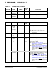
LAN8720A/LAN8720AI 5.3.2 REF_CLK OUT MODE . TABLE 5-2: DEVICE ONLY CURRENT CONSUMPTION AND POWER DISSIPATION (REF_CLK OUT MODE) VDDA3.3 Power Pins(mA) VDDCR Power Pin(mA) VDDIO Power Pin(mA) Total Current (mA) Total Power (mW) Max 28 20 6.3 54 179 Typical 26 19 5.8 50 164 Min 22 15 2.9 39 93 Note 5-11 Max 9.9 13 6.4 30 96 Typical 8.8 12 5.6 26 85 Min 7.1 10 3.0 20 41 Note 5-11 Max 4.5 2.7 0.3 7.5 25 Typical 4.0 1.5 0.2 5.7 19 Min 3.9 1.2 0 5.
LAN8720A/LAN8720AI 5.4 DC Specifications TABLE 5-2: details the non-variable I/O buffer characteristics. These buffer types do not support variable voltage operation. TABLE 5-3: details the variable voltage I/O buffer characteristics. Typical values are provided for 1.8V, 2.5V, and 3.3V VDDIO cases. TABLE 5-3: NON-VARIABLE I/O BUFFER CHARACTERISTICS Parameter Symbol Min Low Input Level VILI -0.3 High Input Level VIHI Negative-Going Threshold VILT 1.
LAN8720A/LAN8720AI TABLE 5-4: VARIABLE I/O BUFFER CHARACTERISTICS Parameter 1.8V Typ 2.5V Typ Symbol Min Low Input Level VILI -0.3 High Input Level VIHI Neg-Going Threshold VILT 0.64 0.83 1.15 Pos-Going Threshold VIHT 0.81 0.99 Schmitt Trigger Hysteresis (VIHT - VILT) VHYS 102 158 Input Leakage (VIN = VSS or VDDIO) IIH -10 Input Capacitance 3.3V Typ Max Units Notes VIS Type Input Buffer V 3.6 V 1.41 1.76 V Schmitt trigger 1.29 1.65 1.
LAN8720A/LAN8720AI Note 5-17 TABLE 5-6: Measured differentially. 10BASE-T TRANSCEIVER CHARACTERISTICS Parameter Symbol Min Typ Max Units Notes Transmitter Peak Differential Output Voltage VOUT 2.2 2.5 2.8 V Note 5-15 Receiver Differential Squelch Threshold VDS 300 420 585 mV — Note 5-18 5.5 Min/max voltages guaranteed as measured with 100 resistive load. AC Specifications This section details the various AC timing specifications of the device.
LAN8720A/LAN8720AI 5.5.2 POWER SEQUENCE TIMING This diagram illustrates the device power sequencing requirements. The VDDIO, VDD1A, VDD2A and magnetics power supplies can turn on in any order provided they all reach operational levels within the specified time period tpon. Device power supplies can turn off in any order provided they all reach 0 volts within the specified time period poff.
LAN8720A/LAN8720AI FIGURE 5-3: POWER-ON NRST & CONFIGURATION STRAP TIMING All External Power Supplies 80% tpurstd tpurstv trstia nRST tcss tcsh Configuration Strap Pins Input totaa todad Configuration Strap Pins Output Drive TABLE 5-8: POWER-ON NRST & CONFIGURATION STRAP TIMING VALUES symbol DESCRIPTION min typ max units tpurstd External power supplies at 80% to nRST deassertion 25 — — mS tpurstv External power supplies at 80% to nRST valid 0 — — nS trstia nRST input assertio
LAN8720A/LAN8720AI 5.5.4 RMII INTERFACE TIMING 5.5.4.1 RMII Timing (REF_CLK Out Mode) The 50MHz REF_CLK OUT timing applies to the case when nINTSEL is pulled-low. In this mode, a 25MHz crystal or clock oscillator must be input on the XTAL1/CLKIN and XTAL2 pins. For more information on REF_CLK Out Mode, see Section 3.7.4.2, REF_CLK Out Mode.
LAN8720A/LAN8720AI 5.5.4.2 RMII Timing (REF_CLK In Mode) The 50MHz REF_CLK IN timing applies to the case when nINTSEL is floated or pulled-high. In this mode, a 50MHz clock must be input on the CLKIN pin. For more information on REF_CLK In Mode, see Section 3.7.4.1, REF_CLK In Mode.
LAN8720A/LAN8720AI 5.5.4.3 RMII CLKIN Requirements TABLE 5-11: RMII CLKIN (REF_CLK) TIMING VALUES Parameter Min Typ Max Units Notes CLKIN frequency 50 — MHz — CLKIN Frequency Drift — ± 50 ppm — — 60 % — — 150 psec p-p – not RMS CLKIN Duty Cycle 40 CLKIN Jitter 5.5.5 SMI TIMING This section specifies the SMI timing of the device. Please refer to Section 3.5, Serial Management Interface (SMI) for additional details.
LAN8720A/LAN8720AI 5.6 Clock Circuit The device can accept either a 25MHz crystal (preferred) or a 25MHz single-ended clock oscillator (±50ppm) input. If the single-ended clock oscillator method is implemented, XTAL2 should be left unconnected and XTAL1/CLKIN should be driven with a nominal 0-3.3V clock signal. It is recommended that a crystal utilizing matching parallel load capacitors be used for the crystal input/output signals (XTAL1/XTAL2). Either a 300uW or 100uW 25MHz crystal may be utilized.
LAN8720A/LAN8720AI Note 5-26 The maximum allowable values for Frequency Tolerance and Frequency Stability are application dependent. Since any particular application must meet the IEEE ±50 PPM Total PPM Budget, the combination of these two values must be approximately ±45 PPM (allowing for aging). Note 5-27 Frequency Deviation Over Time is also referred to as Aging. Note 5-28 The total deviation for the Transmitter Clock Frequency is specified by IEEE 802.3u as ±100 PPM.
LAN8720A/LAN8720AI TABLE 5-14: 100UW 25MHZ CRYSTAL SPECIFICATIONS (CONTINUED) Parameter Symbol Min Nom Max Units Notes Equivalent Series Resistance R1 — — 80 Ohm — XTAL2 Series Resistor Rs 495 500 505 Ohm — Operating Temperature Range — Note 5-35 — +85 oC — XTAL1/CLKIN Pin Capacitance — — 3 typ — pF Note 5-36 XTAL2 Pin Capacitance — — 3 typ — pF Note 5-36 Note 5-31 The maximum allowable values for Frequency Tolerance and Frequency Stability are application depend
LAN8720A/LAN8720AI 6.0 PACKAGE INFORMATION 6.1 24-QFN (Punch) A A1 A2 D/E D1/E1 D2/E2 L b k e Note 1: 2: 3: Min 0.70 0 — 3.90 3.55 2.40 0.30 0.18 0.25 Nominal 0.85 0.02 — 4.00 3.75 2.50 0.40 0.25 — 0.50 BSC Max 1.00 0.05 0.90 4.10 3.95 2.60 0.50 0.30 — Remarks Overall Package Height Standoff Mold Cap Thickness X/Y Body Size X/Y Mold Cap Size X/Y Exposed Pad Size Terminal Length Terminal Width Terminal to Exposed Pad Clearance Terminal Pitch All dimensions are in millimeters unless otherwise noted.
LAN8720A/LAN8720AI 2016 Microchip Technology Inc.
LAN8720A/LAN8720AI 6.2 24-SQFN (Sawn) DS00002165B-page 68 2016 Microchip Technology Inc.
LAN8720A/LAN8720AI 6.3 Note: Tape & Reel Information Standard reel size is 5,000 pieces per reel. 2016 Microchip Technology Inc.
LAN8720A/LAN8720AI DS00002165B-page 70 2016 Microchip Technology Inc.
LAN8720A/LAN8720AI 7.0 APPLICATION NOTES 7.1 Application Diagram The device requires few external components. The voltage on the magnetics center tap can range from 2.5 - 3.3V. 7.1.1 RMII DIAGRAM FIGURE 7-1: SIMPLIFIED APPLICATION DIAGRAM RMII MDIO MDC nINT LAN8720 10/100 PHY 24-QFN RMII Mag RJ45 TXP TXD[1:0] 2 TXEN TXN RXP RXN RXD[1:0] 2 RXER XTAL1/CLKIN LED[2:1] 25MHz 2 nRST XTAL2 Interface 7.1.2 POWER SUPPLY DIAGRAM 2016 Microchip Technology Inc.
LAN8720A/LAN8720AI FIGURE 7-3: HIGH-LEVEL SYSTEM DIAGRAM FOR POWER Analog Supply 3.3V Power to magnetics interface. 6 LAN8720 24-QFN VDDCR 19 VDD1A 1uF CBYPASS VDDDIO Supply 1.8 - 3.3V 9 VDDIO 1 VDD2A CBYPASS CBYPASS CF R 15 24 RBIAS nRST C 12k VSS 7.1.3 TWISTED-PAIR INTERFACE DIAGRAM FIGURE 7-5: COPPER INTERFACE DIAGRAM LAN8720 24-QFN Analog Supply 3.3V VDD2A 49.9 Resistors Magnetic Supply 2.5 - 3.
LAN8720A/LAN8720AI APPENDIX A: TABLE A-1: DATA SHEET REVISION HISTORY REVISION HISTORY Revision Section/Figure/Entry Rev B. (07-15-16) Section 5.1, "Absolute Maximum Ratings*," on page 54 Update to Positive voltage on XTAL1/CLKIN, with respect to ground. Table 5-2, “Non-Variable I/O Buffer Characteristics,” on page 56 Update to min/max values for the last row, ICLK Type Buffer (XTAL1 Input) - High Input Level. All Document converted to Microchip look and feel. Replaces SMSC Rev. 1.4 (08-23-12).
LAN8720A/LAN8720AI THE MICROCHIP WEB SITE Microchip provides online support via our WWW site at www.microchip.com. This web site is used as a means to make files and information easily available to customers.
LAN8720A/LAN8720AI PRODUCT IDENTIFICATION SYSTEM To order or obtain information, e.g., on pricing or delivery, refer to the factory or the listed sales office. PART NO.
LAN8720A/LAN8720AI NOTES: DS00002165B-page 76 2016 Microchip Technology Inc.
LAN8720A/LAN8720AI Note the following details of the code protection feature on Microchip devices: • Microchip products meet the specification contained in their particular Microchip Data Sheet. • Microchip believes that its family of products is one of the most secure families of its kind on the market today, when used in the intended manner and under normal conditions. • There are dishonest and possibly illegal methods used to breach the code protection feature.
Worldwide Sales and Service AMERICAS ASIA/PACIFIC ASIA/PACIFIC EUROPE Corporate Office 2355 West Chandler Blvd. Chandler, AZ 85224-6199 Tel: 480-792-7200 Fax: 480-792-7277 Technical Support: http://www.microchip.com/ support Web Address: www.microchip.