
Datasheet
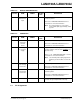
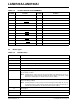
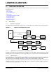

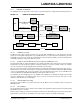

Table Of Contents
- Small Footprint RMII 10/100 Ethernet Transceiver with HP Auto-MDIX Support
- 1.0 Introduction
- 2.0 Pin Description and Configuration
- 3.0 Functional Description
- 3.1 Transceiver
- 3.2 Auto-negotiation
- 3.3 HP Auto-MDIX Support
- 3.4 MAC Interface
- 3.5 Serial Management Interface (SMI)
- 3.6 Interrupt Management
- 3.7 Configuration Straps
- 3.8 Miscellaneous Functions
- 3.9 Application Diagrams
- 4.0 Register Descriptions
- 4.1 Register Nomenclature
- 4.2 Control and Status Registers
- TABLE 4-2: SMI Register Map
- 4.2.1 Basic Control Register
- 4.2.2 Basic Status Register
- 4.2.3 PHY Identifier 1 Register
- 4.2.4 PHY Identifier 2 Register
- 4.2.5 Auto Negotiation Advertisement Register
- 4.2.6 Auto Negotiation Link Partner Ability Register
- 4.2.7 Auto Negotiation Expansion Register
- 4.2.8 Mode Control/Status Register
- 4.2.9 Special Modes Register
- 4.2.10 Symbol Error Counter Register
- 4.2.11 Special Control/Status Indications Register
- 4.2.12 Interrupt Source Flag Register
- 4.2.13 Interrupt Mask Register
- 4.2.14 PHY Special Control/Status Register
- 5.0 Operational Characteristics
- 6.0 Package Information
- 7.0 Application Notes
- Appendix A: Data Sheet Revision History
- The Microchip Web Site
- Customer Change Notification Service
- Customer Support
- Product Identification System
- Worldwide Sales and Service

LAN8720A/LAN8720AI
DS00002165B-page 14 2016 Microchip Technology Inc.
3.0 FUNCTIONAL DESCRIPTION
This chapter provides functional descriptions of the various device features. These features have been categorized into
the following sections:
• Transceiver
• Auto-negotiation
• HP Auto-MDIX Support
• MAC Interface
• Serial Management Interface (SMI)
• Interrupt Management
• Configuration Straps
• Miscellaneous Functions
• Application Diagrams
3.1 Transceiver
3.1.1 100BASE-TX TRANSMIT
The 100BASE-TX transmit data path is shown in Figure 3-1. Each major block is explained in the following subsections.
FIGURE 3-1: 100BASE-TX TRANSMIT DATA PATH
MAC
Tx
Driver
MLT-3
Converter
NRZI
Converter
4B/5B
Encoder
CAT-5RJ45
25MHz by
5 bits
NRZI
MLT-3MLT-3
MLT-3
Scrambler
and PISO
RMII
25MHz
by 4 bits
Ext Ref_CLK
PLL
RMII 50Mhz by 2 bits
MLT-3
Magnetics
125 Mbps Serial
3.1.1.1 100BASE-TX Transmit Data Across the RMII Interface
The MAC controller drives the transmit data onto the TXD bus and asserts TXEN to indicate valid data. The data is
latched by the transceiver’s RMII block on the rising edge of REF_CLK. The data is in the form of 2-bit wide 50MHz data.
3.1.1.2 4B/5B Encoding
The transmit data passes from the RMII block to the 4B/5B encoder. This block encodes the data from 4-bit nibbles to
5-bit symbols (known as “code-groups”) according to Table 3-1. Each 4-bit data-nibble is mapped to 16 of the 32 pos-
sible code-groups. The remaining 16 code-groups are either
used for control information or are not valid.
The first 16 code-groups are referred to by the hexadecimal val
ues of their corresponding data nibbles, 0 through F. The
remaining code-groups are given letter designations with slashes on either side. For example, an IDLE code-group is /
I/, a transmit error code-group is /H/, etc.