
Datasheet
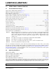
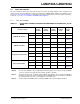

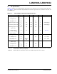

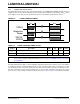
Table Of Contents
- Small Footprint RMII 10/100 Ethernet Transceiver with HP Auto-MDIX Support
- 1.0 Introduction
- 2.0 Pin Description and Configuration
- 3.0 Functional Description
- 3.1 Transceiver
- 3.2 Auto-negotiation
- 3.3 HP Auto-MDIX Support
- 3.4 MAC Interface
- 3.5 Serial Management Interface (SMI)
- 3.6 Interrupt Management
- 3.7 Configuration Straps
- 3.8 Miscellaneous Functions
- 3.9 Application Diagrams
- 4.0 Register Descriptions
- 4.1 Register Nomenclature
- 4.2 Control and Status Registers
- TABLE 4-2: SMI Register Map
- 4.2.1 Basic Control Register
- 4.2.2 Basic Status Register
- 4.2.3 PHY Identifier 1 Register
- 4.2.4 PHY Identifier 2 Register
- 4.2.5 Auto Negotiation Advertisement Register
- 4.2.6 Auto Negotiation Link Partner Ability Register
- 4.2.7 Auto Negotiation Expansion Register
- 4.2.8 Mode Control/Status Register
- 4.2.9 Special Modes Register
- 4.2.10 Symbol Error Counter Register
- 4.2.11 Special Control/Status Indications Register
- 4.2.12 Interrupt Source Flag Register
- 4.2.13 Interrupt Mask Register
- 4.2.14 PHY Special Control/Status Register
- 5.0 Operational Characteristics
- 6.0 Package Information
- 7.0 Application Notes
- Appendix A: Data Sheet Revision History
- The Microchip Web Site
- Customer Change Notification Service
- Customer Support
- Product Identification System
- Worldwide Sales and Service

2016 Microchip Technology Inc. DS00002165B-page 53
LAN8720A/LAN8720AI
5.3 Power Consumption
This section details the device power measurements taken over various operating conditions. Unless otherwise noted,
all measurements were taken with power supplies at nominal values (VDDIO, VDD1A, VDD2A = 3.3V, VDDCR = 1.2V).
See Section 3.8.3, Power-Down Modes for a description of the power down modes. For more information on the REF_-
CLK modes, see Section 3.7.4, nINTSEL: nINT/REFCLKO Configuration.
5.3.1 REF_CLK IN MODE
TABLE 5-1: DEVICE ONLY CURRENT CONSUMPTION A
ND POWER DISSIPATION (REF_CLK IN
MODE)
Power Pin Group
VDDA3.3
Power
PinS(mA)
VDDCR
Power
pin(mA)
VDDIO
po
wer
pin(mA)
Total
Current
(mA)
Total
Power
(mW)
100BASE-TX /w traffic
Max 28 21 0.6 49 159
Typical 26 19 0.5 45 148
Min 23 18 0.3 41 96
Note 5-8
10BASE-T /w traffic
Max 9.7 13 0.6 24 77
Typical 8.9 12 0.5 22 70
Min 8.3 12 0.3 20 42
Note 5-8
Energy Detect Power Down
Max 4.2 3.0 0.2 7.4 25
Typical 4.1 1.9 0.2 6.2 21
Min 3.9 1.9 0 5.8 16
Note 5-8
General Power Down
Max 0.4 2.8 0.2 3.4 11.2
Typical 0.3 1.8 0.2 2.3 7.6
Min 0.3 1.7 0 2 3.0
Note 5-8
Note 5-6 The curren
t at VDDCR is either supplied by the internal regulator from current entering at VDD2A,
or from an external 1.2V supply when the internal regulator is disabled.
Note 5-7 Cu
rrent measurements do not include power applied to the magnetics or the optional external LEDs.
The Ethernet component current is typically 41mA in 100BASE-TX mode and 100mA in 10BASE-T
mode, independent of the 2.5V or 3.3V supply rail of the transformer.
Note 5-8 Ca
lculated with full flexPWR features activated: VDDIO=1.8V & internal regulator disabled.