
Datasheet

10/100 Non-PCI Ethernet Single Chip MAC + PHY
Datasheet
SMSC LAN91C111 REV C 131 Revision 1.92 (06-27-11)
DATASHEET
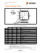
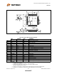
Chapter 15 Package Outlines
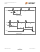
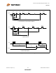
Notes:
1. Controlling Unit: millimeter
2. Tolerance on the position of the leads is ± 0.035 mm maximum
3. Package body dimensions D1 and E1 do not include the mold protrusion.
Maximum mold protrusion is 0.25 mm
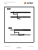
4. Dimension for foot length L measured at the gauge plane 0.25 mm above the seating plane is 0.78-1.08 mm.
5. Details of pin 1 identifier are optional but must be located within the zone indicated.
6. Shoulder widths must conform to JEDEC MS-026 dimension 'S' of a minimum of 0.20mm.
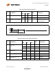
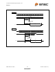
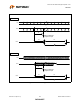
Figure 15.1 128 Pin TQFP Package Outline, 14X14X1.0 Body
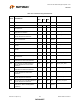
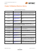
Table 15.1 128 Pin TQFP Package Parameters
MIN NOMINAL MAX REMARK
A ~ ~ 1.20 Overall Package Height
A1 0.05 ~ 0.15 Standoff
A2 0.95 1.00 1.05 Body Thickness
D 15.80 16.00 16.20 X Span
D/2 7.90 8.00 8.10
1
/
2
X Span Measure from Centerline
D1 13.80 14.00 14.20 X body Size
E 15.80 16.00 16.20 Y Span
E/2 7.90 8.00 8.10
1
/
2
Y Span Measure from Centerline
E1 13.80 14.00 14.20 Y body Size
H 0.09 ~ 0.20 Lead Frame Thickness
L 0.45 0.60 0.75 Lead Foot Length from Centerline
L1 ~ 1.00 ~ Lead Length
e 0.40 Basic Lead Pitch
q0
o
~7
o
Lead Foot Angle
W 0.13 0.18 0.23 Lead Width
R1 0.08 ~ ~ Lead Shoulder Radius
R2 0.08 ~ 0.20 Lead Foot Radius
ccc ~ ~ 0.0762 Coplanarity (Assemblers)
ccc ~ ~ 0.08 Coplanarity (Test House)