
User`s guide


MCP1630 DUAL BUCK DEMO
BOARD USER’S GUIDE
© 2005 Microchip Technology Inc. DS51531A-page 7
Chapter 2. Installation and Operation
2.1 INTRODUCTION
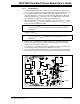
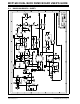
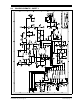
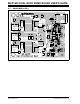
The MCP1630 Dual Buck Demo Board demonstrates Microchip’s MCP1630
high-speed PWM, used in an adjustable, dual-output, buck regulator application. The
MCP1630 is a high-speed, microcontroller-adaptable, PWM that, when used in
conjunction with a microcontroller, will control the power system duty cycle to provide
output voltage regulation. The PIC16F684 microcontroller can be used to regulate
output voltage or current, switching frequency and setting maximum duty cycle. The
MCP1630 generates duty cycle, provides fast overcurrent protection and utilizes
variable external inputs. External signals include the input oscillator and the reference
voltage. The power train signals include the current sense and the feedback voltage.
The output signal is a square-wave pulse. The power train used for the MCP1630 Dual
Buck Demo Board is a dual synchronous buck regulator.
2.2 FEATURES
The MCP1630 Dual Buck Demo Board has the following features:
• Input Voltage Range: +9.0V to +13.5V
• Adjustable Output Voltage Capable of Calibration
• Sequencing or Tracking Outputs
• Outputs are180° out of phase, each capable of 20A
• Independent Overcurrent Protection
• Independent Overtemperature Protection
• Input Overvoltage and Undervoltage Lockout (UVLO)
• Power Good Indication (LED) with Adjustable Delay
• Switching Frequency Dithering
2.3 GETTING STARTED
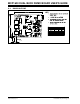
The MCP1630 Dual Buck Demo Board is fully assembled and tested over its range of
input voltage, output voltage and output current. This board requires the use of an
external input voltage source (+9.0V to +13.5V) and external load (electronic or
resistive).
Note: It is recommended that a minimum 300 linear feet per minute of airflow
blown directly across the board to cool the power dissipating components
when operating above 10A loads.