MCP2200 USB 2.
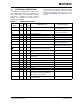
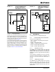
MCP2200 Block Diagram GP5 GP3 GP1 TXLED/ RXLED/ GP4 GP2 GP0 GP7 GP6 Configuration and Control Registers 256 Byte EEPROM GPIO USB LEDs TX RX CTS D+ UART Controller USB Protocol Controller Control USB Transceiver RTS DVUSB Baud Generator State USB Clock Clock DS22228B-page 2 VSS Osc Reset 3.3V LDO VSS OSC1 OSC2 RST VDD 2011 Microchip Technology Inc.
MCP2200 1.0 FUNCTIONAL DESCRIPTION The MCP2200 is a USB-to-UART serial converter which enables USB connectivity in applications that have a UART interface. The device reduces external components by integrating the USB termination resistors. The MCP2200 also has 256 bytes of integrated user EEPROM. TABLE 1-1: Pin Name The MCP2200 has eight general purpose input/output pins. Four pins have alternate functions to indicate USB and communication status. See Table 1-1 and Section 1.
MCP2200 1.1 Supported Operating Systems 1.3.1 INITIAL CONFIGURATION Windows XP (SP2 and later), Vista, and Windows 7 operating systems are supported. The default UART configuration is 19200, 8, N, 1. The default start up baud rate can be changed using the Microchip-supplied configuration PC tool. 1.1.1 Alternatively, a custom configuration tool can be created using the Microchip-supplied DLL to set the baud rate, as well as other parameters. See Section 2.0 “Configuration” for details.
MCP2200 EQUATION 1-1: SOLVING FOR ACTUAL BAUD RATE 12MHz ActualRate = ------------------int x Where: 1.3.3 12MHz x = ----------------------------------DesiredBaud CUSTOM BAUD RATES Custom baud rates are configured by sending the SET_LINE_CODING USB command, or by using the DLL. See Section 2.0 “Configuration” for more information. 1.3.4 HARDWARE FLOW CONTROL 1.4 USB Protocol Controller The USB controller in the MCP2200 is full-speed USB 2.0 compliant.
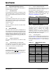
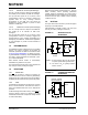
MCP2200 1.5.2.1 Internal Power Supply Details MCP2200 offers various options for power supply. To meet the required USB signaling levels, MCP2200 device incorporates an internal LDO used solely by the USB transceiver, in order to present the correct D+/Dvoltage levels. Figure 1-2 shows the internal connections of the USB transceiver LDO in relation with the VDD power supply rail. The output of the USB transceiver LDO is tied to the VUSB line.
MCP2200 FIGURE 1-4: 5V (USB Bus) or external power supply TYPICAL POWER SUPPLY OPTION USING THE 5V PROVIDED BY THE USB FIGURE 1-5: USING AN EXTERNALLY PROVIDED 3.3V POWER SUPPLY 5V (USB Bus) or external External 3.3V power supply VDD LDO VDD IN IN LDO 3.3V LDO 3.3V VUSB D+ D- 1.5.2.3 D+ USB Transceiver 3.3V Self Powered Typically, many embedded applications are using 3.3V power supplies. When such an option is available in the target system, MCP2200 can be powered up from the existing 3.
MCP2200 1.6.1.3 RxLED Pin Function (IN Message) The ‘Rx’ in the pin name is in respect to the USB host. The RxLED pin is an indicator for USB ‘IN’ messages. This pin will either pulse low for a period of time (configurable for ~100 ms or ~200 ms), or toggle to the opposite state for every message received (IN message) by the USB host. This allows the application to count messages or provide a visual indication of USB traffic. 1.6.1.
MCP2200 2.0 CONFIGURATION The MCP2200 is configured by writing special commands using the HID interface. Configuration can be achieved using the configuration utility provided by Microchip. Alternatively, a custom utility can be developed by using the DLL available on the MCP2200 product page. 2.1 Configuration Utility The configuration utility provided by Microchip allows the user to configure the MCP2200 to custom defaults.
MCP2200 FIGURE 2-1: DS22228B-page 10 CONFIGURATION UTILITY 2011 Microchip Technology Inc.
MCP2200 2.3 Simple Configuration and I/O DLL To help the user develop a custom configurator, Microchip provides a DLL that uses Microsoft®.NET Framework 3.5. There is documentation about drivers and utilities on the MCP2200 product page at www.microchip.com (in the Software section) with information on associating the DLL with a Visual C++ project. TABLE 2-2: 2.3.1 SIMPLE I/O DLL CALLS Table 2-2 lists the functions provided by the DLL to allow the configuration of the device and control of the I/O.
MCP2200 TABLE 2-2: CONFIGURATION FUNCTIONS (CONTINUED) Category and Function Name Summary (Continued) bool SimpleIOClass::fnRxLED (unsigned int mode) Section 2.3.1.6 bool SimpleIOClass::fnSetBaudRate (unsigned long BaudRateParam) Section 2.3.1.7 bool SimpleIOClass::fnSuspend(unsigned int onOff) Section 2.3.1.8 bool SimpleIOClass::fnTxLED (unsigned int mode) Section 2.3.1.9 bool SimpleIOClass::fnULoad(unsigned int onOff) Section 2.3.1.
MCP2200 2.3.1.2 ConfigureIO Function: bool SimpleIOClass::ConfigureIO (unsigned char IOMap) Summary: Configures the GPIO pins for Digital Input, Digital Output. Description: GPIO Pins can be configured as Digital Input, Digital Output. Precondition: VID and PID must be previously set via a call to InitMCP2200(VID, PID).
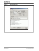
MCP2200 2.3.1.4 ConfigureMCP2200 Function: bool SimpleIOClass::ConfigureIoDefaultOutput (unsigned long BaudRateParam, unsigned int RxLEDMode, unsigned int TxLEDMode, bool FLOW, bool ULOAD, bool SSPND) Summary: Configures the device. Description: Sets the default GPIO designation, baud rate, TX/RX LED modes, flow control. Precondition: VID and PID must be previously set via a call to InitMCP2200(VID, PID). Parameters: 1. 2. 3. 4. 5. 6. 7.
MCP2200 2.3.1.6 fnRxLED Function: bool SimpleIOClass::fnRxLED (unsigned int mode) Summary: Configures the Rx LED mode. Rx LED configuration will be stored in NVRAM. Description: Sets the Rx LED mode to one of the possible values. Precondition: VID and PID must be previously set via a call to InitMCP2200(VID, PID). Parameters: mode (constant): OFF, TOGGLE, BLINKSLOW, BLINKFAST Returns: This function returns True if the transmission is successful and returns False if the transmission fails.
MCP2200 EXAMPLE 2-8: if (SimpleIOClass::fnSuspend(1) == SUCCESS) lblStatusBar->Text = “Success”; else lblStatusBar->Text = “Invalid command ” + SimpleIOClass::LastError; 2.3.1.9 fnTxLED Function: bool SimpleIOClass::fnTxLED (unsigned int mode) Summary: Configures the Tx LED mode. Tx LED configuration will be stored in NVRAM. Description: Sets the Tx LED mode to one of the possible values. Precondition: VID and PID must be previously set via a call to InitMCP2200(VID, PID).
MCP2200 2.3.1.11 GetDeviceInfo Function: String^ SimpleIOClass::GetDeviceInfo (unsigned int uiDeviceNo) Summary: Returns the path name for one of the connected devices. Description: The function will return the path name for the given device ID. Precondition: At least one call to the InitMCP2200() is required in order to initiate a DLL search for the compatible devices. VID and PID must be previously set via a call to InitMCP2200(VID, PID).
MCP2200 EXAMPLE 2-13: lblStatusBar->Text = SimpleIOClass::GetSelectedDevice(); 2.3.1.14 GetSelectedDeviceInfo Function: String^ SimpleIOClass::GetSelectedDeviceInfo(void) Summary: Returns the selected device path name. Description: The function returns a string containing the unique path name of the selected device. Precondition: At least one call to the InitMCP2200() is required in order to initiate a DLL search for the compatible devices.
MCP2200 EXAMPLE 2-16: unsigned int rv; if (SimpleIOClass::IsConnected ()) { lblStatusBar->Text = “Device connected”; } else lblStatusBar->Text = “Device Disconnected”; 2.3.1.17 ReadEEPROM Function: int SimpleIOClass::ReadEEPROM (unsigned int uiEEPAddress) Summary: Reads a byte from the EEPROM. Description: Reads a byte from the EEPROM at the given address. Precondition: At least one call to the InitMCP2200() is required in order to initiate a DLL search for the compatible devices.
MCP2200 2.3.1.19 ReadPinValue Function: int SimpleIOClass::ReadPinValue(unsigned int pin) Summary: Reads the specified pin. Description: Reads the specified pin and returns the value as the return value. If the pin has been configured as a digital input, the return value will be either ‘0’ or ‘1’. If an error occurs, the function will return a value of 0x8000. Precondition: Must be previously configured as an input via a ConfigureIO call.
MCP2200 2.3.1.21 ReadPortValue Function: int SimpleIOClass::ReadPortValue() Summary: Reads the GPIO port as digital input. Description: Reads the GPIO port and returns the value of the port. This provides a method to read all pins simultaneously, instead of one-by-one. In case of an error, the returned value will be 0x8000. Precondition: Must be previously configured as an input via a ConfigureIO call. VID and PID must be previously set via a call to InitMCP2200(VID, PID). Parameters: None.
MCP2200 2.3.1.23 SetPin Function: bool SimpleIOClass::SetPin(unsigned int pin) Summary: Sets the specified pin. Description: Sets the specified pin to logic ‘1’. Precondition: Must be previously configured as an output via a ConfigureIO or ConfigureIoDefaultOutput call. VID and PID must be previously set via a call to InitMCP2200(VID, PID).
MCP2200 2.3.1.25 WritePort Function: bool SimpleIOClass::WritePort(unsigned int portValue) Summary: Writes a value to the GPIO port. Description: Writes the GPIO port. This provides a means to write all pins at simultaneously, instead of one-byone. Precondition: Must be previously configured as an output via a ConfigureIO call. VID and PID must be previously set via a call to InitMCP2200(VID, PID). Parameters: portValue - byte value to set on the port.
MCP2200 NOTES: DS22228B-page 24 2011 Microchip Technology Inc.
MCP2200 3.0 ELECTRICAL CHARACTERISTICS Absolute Maximum Ratings (†) Ambient temperature under bias......................................................................................................... -40°C to +85°C Storage temperature ........................................................................................................................ -65°C to +150°C Voltage on VDD with respect to VSS ...................................................................................................
MCP2200 3.1 DC CHARACTERISTICS DC Characteristics Param No. D001 Characteristic Operating Conditions (unless otherwise indicated): 3.0V VDD 5.5V at -40C TA +85C (I-Temp) Sym Min Typ Max Units Supply Voltage VDD 3.0 — 5.5 V Power-on Reset Release Voltage VPOR Power-on Reset Rearm Voltage D003 VDD Rise Rate to Ensure Power-on Reset D004 Supply Current D005 1.6 V 0.8 V 0.05 — — VDD = 3.0V — 10 12 mA VDD = 5.0V — 13 15 mA — 9 — µA — — 0.
MCP2200 FIGURE 3-1: POR AND POR REARM WITH SLOW RISING VDD VDD VPOR VPORR VSS NPOR(1) POR REARM VSS TPOR(3) TVLOW(2) Note 1: 2: 3: TABLE 3-1: USB MODULE SPECIFICATIONS DC Characteristics Param No. When NPOR is low, the device is held in Reset. TPOR 1 s typical. TVLOW 2.7 s typical. Characteristic Operating Conditions (unless otherwise indicated): 3.0V VDD 5.5V at -40C TA +85C (I-Temp) Sym Min Typ Max Units Conditions VUSB 3.0 — 3.
MCP2200 TABLE 3-2: THERMAL CONSIDERATIONS Standard Operating Conditions (unless otherwise stated) Operating temperature -40C TA +85C (I-Temp) Param No. Sym TH01 θJA Thermal Resistance Junction to Ambient TH02 θJC Thermal Resistance Junction to Case TH03 TH04 TJMAX PD Maximum Junction Temperature Power Dissipation TH05 TH06 TH07 Note 1: 2: 3: Characteristic PINTERNAL Internal Power Dissipation PI/O I/O Power Dissipation Typ Units 85.2 108.1 36.1 24 24 1.
MCP2200 3.2 AC Characteristics 3.2.1 TIMING PARAMETER SYMBOLOGY The timing parameter symbols have been created in one of the following formats: 1. TppS2ppS T F Frequency E Error Lowercase letters (pp) and their meanings: pp io Input or Output pin rx Receive bitclk RX/TX BITCLK drt Device Reset Timer Uppercase letters and their meanings: S F Fall H High I Invalid (high-impedance) L Low 3.2.2 2.
MCP2200 3.2.3 TIMING DIAGRAMS AND SPECIFICATIONS TABLE 3-4: RESET, OSCILLATOR START-UP TIMER AND POWER-UP TIMER PARAMETERS Standard Operating Conditions (unless otherwise stated) Operating Temperature -40°C TA +85°C Param No. Sym 30 TRST 31 32 Characteristic MCLR Pulse Width (low) TPWRT Power-up timer TOST Oscillator startup time Min Typ† Max Units 2 — — μs 40 65 140 ms — 1024 — TOST Conditions * These parameters are characterized but not tested.
MCP2200 4.0 PACKAGING INFORMATION 4.1 Package Marking Information 20-Lead QFN Example XXXXX XXXXXX XXXXXX YWWNNN 20-Lead SOIC MCP2200 e3 I/MQ^^ 1042256 Example: MCP2200 e3 I/SO ^^ 1042256 XXXXXXXXXXXXXX XXXXXXXXXXXXXX XXXXXXXXXXXXXX YYWWNNN 20-Lead SSOP Example: XXXXXXXXXXX XXXXXXXXXXX YYWWNNN Legend: XX...
MCP2200 20-Lead Plastic Quad Flat, No Lead Package (MQ) 5x5x0.9 mm Body [QFN] Note: For the most current package drawings, please see the Microchip Packaging Specification located at http://www.microchip.com/packaging Microchip Technology Drawing C04-120A DS22228B-page 32 2011 Microchip Technology Inc.
MCP2200 Note: For the most current package drawings, please see the Microchip Packaging Specification located at http://www.microchip.com/packaging 2011 Microchip Technology Inc.
MCP2200 /HDG 3ODVWLF 6PDOO 2XWOLQH 62 ± :LGH PP %RG\ >62,&@ 1RWH )RU WKH PRVW FXUUHQW SDFNDJH GUDZLQJV SOHDVH VHH WKH 0LFURFKLS 3DFNDJLQJ 6SHFLILFDWLRQ ORFDWHG DW KWWS ZZZ PLFURFKLS FRP SDFNDJLQJ D N E E1 NOTE 1 1 2 3 e b α h h A A2 c φ L A1 8QLWV 'LPHQVLRQ /LPLWV 1XPEHU RI 3LQV β L1 0,//,0(7(56 0,1 1 120 0$; 3LWFK H 2YHUDOO +HLJKW $ ± %6& ± 0ROGHG 3DFNDJH 7KLFNQHVV $ ± ± 6WDQGRII $ ± 2YHUDOO :LGWK ( 0ROGHG 3DFNDJH :LGWK (
MCP2200 Note: For the most current package drawings, please see the Microchip Packaging Specification located at http://www.microchip.com/packaging 2011 Microchip Technology Inc.
MCP2200 /HDG 3ODVWLF 6KULQN 6PDOO 2XWOLQH 66 ± PP %RG\ >6623@ 1RWH )RU WKH PRVW FXUUHQW SDFNDJH GUDZLQJV SOHDVH VHH WKH 0LFURFKLS 3DFNDJLQJ 6SHFLILFDWLRQ ORFDWHG DW KWWS ZZZ PLFURFKLS FRP SDFNDJLQJ D N E E1 NOTE 1 1 2 e b c A2 A φ A1 L1 8QLWV 'LPHQVLRQ /LPLWV 1XPEHU RI 3LQV L 0,//,0(7(56 0,1 1 120 0$; 3LWFK H 2YHUDOO +HLJKW $ ± %6& ± 0ROGHG 3DFNDJH 7KLFNQHVV $ 6WDQGRII $ ± ± 2YHUDOO :LGWK ( 0ROGHG 3DFNDJH
MCP2200 Note: For the most current package drawings, please see the Microchip Packaging Specification located at http://www.microchip.com/packaging 2011 Microchip Technology Inc.
MCP2200 NOTES: DS22228B-page 38 2011 Microchip Technology Inc.
MCP2200 APPENDIX A: REVISION HISTORY Revision B (March 2011) The following is the list of modifications: 1. 2. 3. Added new section Section 1.5.2 “MCP2200 Power Options”. Updated entire Section 2.3 “Simple Configuration and I/O DLL”. Added values to parameters TH01 and TH02 for the 20-Lead 5x5 QFN package in Table 3-2. Revision A (March 2010) Original Release of this Document. 2011 Microchip Technology Inc.
MCP2200 NOTES: DS22228B-page 40 2011 Microchip Technology Inc.
MCP2200 PRODUCT IDENTIFICATION SYSTEM To order or obtain information, e.g., on pricing or delivery, contact your local Microchip sales office. PART NO. X /XX Device Temperature Range Package Device MCP2200: MCP2200T: Reel) Examples: a) USB-to-UART serial converter USB-to-UART serial converter (Tape and Temperature Range I = Package MQ = Plastic Quad Flat, No Lead Package 5x5x0.9 mm Body (QFN), 20-Lead = Plastic Small Outline - Wide, 7.
MCP2200 NOTES: DS22228B-page 42 2011 Microchip Technology Inc.
Note the following details of the code protection feature on Microchip devices: • Microchip products meet the specification contained in their particular Microchip Data Sheet. • Microchip believes that its family of products is one of the most secure families of its kind on the market today, when used in the intended manner and under normal conditions. • There are dishonest and possibly illegal methods used to breach the code protection feature.
Worldwide Sales and Service AMERICAS ASIA/PACIFIC ASIA/PACIFIC EUROPE Corporate Office 2355 West Chandler Blvd. Chandler, AZ 85224-6199 Tel: 480-792-7200 Fax: 480-792-7277 Technical Support: http://support.microchip.com Web Address: www.microchip.