
Datasheet

2011 Microchip Technology Inc. DS22288A-page 3
MCP2210
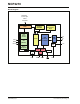
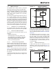
1.0 FUNCTIONAL DESCRIPTION
The MCP2210 device is a USB-to-SPI Master
converter which enables USB connectivity in
applications that have an SPI interface. The device
reduces external components by integrating the USB
termination resistors.
The MCP2210 also has 256 bytes of integrated user
EEPROM.
The MCP2210 has nine general purpose input/output
pins. Seven pins have alternate functions to indicate
USB and communication status. See Table 1 - 1 and
Section 1.6 “GP Module” for details about the pin
functions.
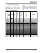
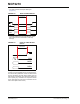
TABLE 1-1: PINOUT DESCRIPTION
MCP2210
Symbol Type
Standard Function
(GPIO)
Alternate Function 1
(Chip Selects)
Alternate Function 2
(dedicated functions)
Description
QFN
SOIC,
SSOP
14RSTI— — —
Reset input
2 5 GP0 I/O GPIO0 CS0 — General Purpose I/O
3 6 GP1 I/O GPIO1 CS1 — General Purpose I/O
4 7 GP2 I/O GPIO2 CS2 USB Suspend General Purpose I/O
5 8 GP3 I/O GPIO3 CS3 SPI Transfer Traffic LED General Purpose I/O
6 9 MOSI O — — — SPI Master output
7 10 GP4 I/O GPIO4 CS4 USB Low Power General Purpose I/O
8 11 SCK O — — — SPI Clock output
9 12 GP5 I/O GPIO5 CS5 USB Configured General Purpose I/O
10 13 MISO I — — — SPI Master input
11 14 GP6 I/O GPIO6 CS6 External Interrupt General Purpose I/O
12 15 GP7 I/O GPIO7 CS7 SPI Bus Release ACK General Purpose I/O
13 16 GP8 I/O GPIO8 CS8 SPI Bus Release REQ General Purpose I/O
14 17 V
USB USB — — — USB Regulator output
15 18 D- USB — — — USB D-
16 19 D+ USB — — — USB D+
17 20 V
SS GND — — — Ground
18 1 VDD P— — — Power
19 2 OSC1 I — — — Oscillator input
20 3 OSC2 O — — — Oscillator output