
Datasheet


© 2007 Microchip Technology Inc. DS21919E-page 9
MCP23008/MCP23S08
1.5 GPIO Port
The GPIO module contains the data port (GPIO),
internal pull up resistors and the Output Latches
(OLAT).
Reading the GPIO register reads the value on the port.
Reading the OLAT register only reads the OLAT, not
the actual value on the port.
Writing to the GPIO register actually causes a write to
the OLAT. Writing to the OLAT register forces the
associated output drivers to drive to the level in OLAT.
Pins configured as inputs turn off the associated output
driver and put it in high-impedance.
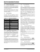
1.6 Configuration and Control
Registers
The Configuration and Control blocks contain the
registers as shown in Table 1-3.
TABLE 1-3: CONFIGURATION AND CONTROL REGISTERS
Register
Name
Address
(hex)
bit 7 bit 6 bit 5 bit 4 bit 3 bit 2 bit 1 bit 0
POR/RST
value
IODIR 00 IO7 IO6 IO5 IO4 IO3 IO2 IO1 IO0 1111 1111
IPOL 01 IP7 IP6 IP5 IP4 IP3 IP2 IP1 IP0 0000 0000
GPINTEN 02 GPINT7 GPINT6 GPINT5 GPINT4 GPINT3 GPINT2 GPINT1 GPINT0 0000 0000
DEFVAL 03 DEF7 DEF6 DEF5 DEF4 DEF3 DEF2 DEF1 DEF0 0000 0000
INTCON 04 IOC7 IOC6 IOC5 IOC4 IOC3 IOC2 IOC1 IOC0 0000 0000
IOCON 05
— — SREAD DISSLW HAEN* ODR INTPOL — --00 000-
GPPU 06 PU7 PU6 PU5 PU4 PU3 PU2 PU1 PU0 0000 0000
INTF 07 INT7 INT6 INT5 INT4 INT3 INT2 INT1 INTO 0000 0000
INTCAP 08 ICP7 ICP6 ICP5 ICP4 ICP3 ICP2 ICP1 ICP0 0000 0000
GPIO 09 GP7GP6GP5GP4GP3GP2GP1GP00000 0000
OLAT 0A OL7 OL6 OL5 OL4 OL3 OL2 OL1 OL0 0000 0000
* Not used on the MCP23008.