
Datasheet

MCP23018/MCP23S18
DS22103A-page 4 © 2008 Microchip Technology Inc.
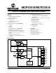
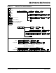
1.0 DEVICE OVERVIEW
The MCP23X18 device provides 16-bit, general pur-
pose parallel I/O expansion for I
2
C bus or SPI
applications. The two devices differ only in the serial
interface.
• MCP23018 - I
2
C interface
• MCP23S18 - SPI interface
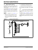
The MCP23X18 consists of multiple 8-bit configuration
registers for input, output and polarity selection. The
system master can enable the I/Os as either inputs or
outputs by writing the I/O configuration bits. The data
for each input or output is kept in the corresponding
input or output register. The polarity of the input port
register can be inverted with the polarity inversion
register. All registers can be read by the system master.
The 16-bit I/O port functionally consists of two (2) 8-bit
ports (PORTA and PORTB). The MCP23X18 can be
configured to operate in 8-bit mode or 16-bit mode via
IOCON.BANK.
There are two interrupt pins, INTA and INTB which can
be associated with their respective ports, or can be
logically OR’ed together so both pins will activate if
either port causes an interrupt.
The interrupt output can be configured to activate
under two conditions (mutually exclusive):
1. When any input state differs from its
corresponding input port register state. This is
used to indicate to the system master that an
input state has changed.
2. When an input state differs from a pre-
configured register value (DEFVAL register).
The Interrupt Capture register captures port values at
the time of the interrupt, thereby saving the condition
that caused the interrupt.
The Power-on Reset (POR) sets the registers to their
default values and initializes the device state machine.
The hardware address pin is used to determine the
device address.