
Datasheet


© 2007 Microchip Technology Inc. DS21291F-page 35
MCP2510
5.0 BIT TIMING
All nodes on a given CAN bus must have the same
nominal bit rate. The CAN protocol uses Non Return to
Zero (NRZ) coding which does not encode a clock
within the data stream. Therefore, the receive clock
must be recovered by the receiving nodes and syn-
chronized to the transmitters clock.
As oscillators and transmission time may vary from
node to node, the receiver must have some type of
Phase Lock Loop (PLL) synchronized to data transmis-
sion edges to synchronize and maintain the receiver
clock. Since the data is NRZ coded, it is necessary to
include bit stuffing to ensure that an edge occurs at
least every six bit times, to maintain the Digital Phase
Lock Loop (DPLL) synchronization.
The bit timing of the MCP2510 is implemented using a
DPLL that is configured to synchronize to the incoming
data, and provide the nominal timing for the transmitted
data. The DPLL breaks each bit time into multiple seg-
ments made up of minimal periods of time called the
time quanta (T
Q).
Bus timing functions executed within the bit time frame,
such as synchronization to the local oscillator, network
transmission delay compensation, and sample point
positioning, are defined by the programmable bit timing
logic of the DPLL.
All devices on the CAN bus must use the same bit rate.
However, all devices are not required to have the same
master oscillator clock frequency. For the different
clock frequencies of the individual devices, the bit rate
has to be adjusted by appropriately setting the baud
rate prescaler and number of time quanta in each seg-
ment.
The nominal bit rate is the number of bits transmitted
per second assuming an ideal transmitter with an ideal
oscillator, in the absence of resynchronization. The
nominal bit rate is defined to be a maximum of 1 Mb/s.
Nominal Bit Time is defined as:
T
BIT = 1 / NOMlNAL BlT RATE
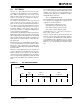
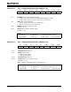
The nominal bit time can be thought of as being divided
into separate non-overlapping time segments. These
segments are shown in Figure 5-1.
- Synchronization Segment (Sync_Seg)
- Propagation Time Segment (Prop_Seg)
- Phase Buffer Segment 1 (Phase_Seg1)
- Phase Buffer Segment 2 [Phase_Seg2)
Nominal Bit Time = T
Q * (Sync_Seg + Prop_Seg +
Phase_Seg1 + Phase_Seg2)
The time segments and also the nominal bit time are
made up of integer units of time called time quanta or
T
Q (see Figure 5-1). By definition, the nominal bit time
is programmable from a minimum of 8 T
Q to a maxi-
mum of 25 T
Q. Also, by definition the minimum nominal
bit time is 1 µs, corresponding to a maximum 1 Mb/s
rate.
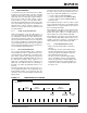
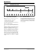
FIGURE 5-1: BIT TIME PARTITIONING
Input Signal
Sync
Prop
Segment
Phase
Segment 1
Phase
Segment 2
Sample Point
TQ