
Datasheet

MCP2510
DS21291F-page 6 © 2007 Microchip Technology Inc.
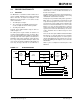
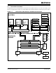
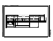
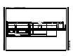
1.3 CAN Protocol Engine
The CAN protocol engine combines several functional
blocks, shown in Figure 1-4. These blocks and their
functions are described below.
1.4 Protocol Finite State Machine
The heart of the engine is the Finite State Machine
(FSM). This state machine sequences through mes-
sages on a bit by bit basis, changing states as the fields
of the various frame types are transmitted or received.
The FSM is a sequencer controlling the sequential data
stream between the TX/RX Shift Register, the CRC
Register, and the bus line. The FSM also controls the
Error Management Logic (EML) and the parallel data
stream between the TX/RX Shift Registers and the
buffers. The FSM insures that the processes of recep-
tion, arbitration, transmission, and error signaling are
performed according to the CAN protocol. The auto-
matic retransmission of messages on the bus line is
also handled by the FSM.
1.5 Cyclic Redundancy Check
The Cyclic Redundancy Check Register generates the
Cyclic Redundancy Check (CRC) code which is trans-
mitted after either the Control Field (for messages with
0 data bytes) or the Data Field, and is used to check the
CRC field of incoming messages.
1.6 Error Management Logic
The Error Management Logic is responsible for the
fault confinement of the CAN device. Its two counters,
the Receive Error Counter (REC) and the Transmit
Error Counter (TEC), are incremented and decre-
mented by commands from the Bit Stream Processor.
According to the values of the error counters, the CAN
controller is set into the states error-active, error-pas-
sive or bus-off.
1.7 Bit Timing Logic
The Bit Timing Logic (BTL) monitors the bus line input
and handles the bus related bit timing according to the
CAN protocol. The BTL synchronizes on a recessive to
dominant bus transition at Start of Frame (hard syn-
chronization) and on any further recessive to dominant
bus line transition if the CAN controller itself does not
transmit a dominant bit (resynchronization). The BTL
also provides programmable time segments to com-
pensate for the propagation delay time, phase shifts,
and to define the position of the Sample Point within the
bit time. The programming of the BTL depends upon
the baud rate and external physical delay times.
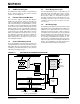
FIGURE 1-4: CAN PROTOCOL ENGINE BLOCK DIAGRAM
Bit Timing Logic
CRC<14:0>
Comparator
Receive<7:0> Transmit<7:0>
Sample<2:0>
Majority
Decision
StuffReg<5:0>
Comparator
Transmit Logic
Receive
Error Counter
Transmit
Error Counter
Protocol
FSM
RX
SAM
BusMon
Rec/Trm Addr.
RecData<7:0>
TrmData<7:0>
Shift<14:0>
(Transmit<5:0>, Receive<7:0>)
TX
REC
TEC
ErrPas
BusOff
Interface to Standard Buffer