
Datasheet


MCP2510
DS21291F-page 68 © 2007 Microchip Technology Inc.
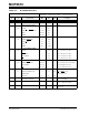
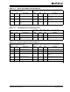
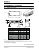
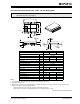
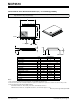
20-Lead Plastic Thin Shrink Small Outline (ST) – 4.4 mm Body [TSSOP]
N
otes:
1
. Pin 1 visual index feature may vary, but must be located within the hatched area.
2
. Dimensions D and E1 do not include mold flash or protrusions. Mold flash or protrusions shall not exceed 0.15 mm per side.
3
. Dimensioning and tolerancing per ASME Y14.5M.
BSC: Basic Dimension. Theoretically exact value shown without tolerances.
REF: Reference Dimension, usually without tolerance, for information purposes only.
Note: For the most current package drawings, please see the Microchip Packaging Specification located at
http://www.microchip.com/packaging
Units MILLIMETERS
Dimension Limits MIN NOM MAX
Number of Pins N 20
Pitch e 0.65 BSC
Overall Height A – – 1.20
Molded Package Thickness A2 0.80 1.00 1.05
Standoff A1 0.05 – 0.15
Overall Width E 6.40 BSC
Molded Package Width E1 4.30 4.40 4.50
Molded Package Length D 6.40 6.50 6.60
Foot Length L 0.45 0.60 0.75
Footprint L1 1.00 REF
Foot Angle φ 0° – 8°
Lead Thickness c 0.09 – 0.20
Lead Width b 0.19 – 0.30
D
E
E1
NOTE 1
1
2
b
e
A
A1
A2
c
L1
L
φ
N
Microchip Technology Drawing C04-088
B