
User's Manual
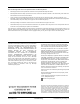
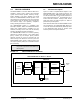
Table Of Contents
- Features:
- Operational:
- RF/Analog Features:
- MAC/Baseband Features:
- Table of Contents
- Most Current Data Sheet
- Errata
- Customer Notification System
- 1.0 Device Overview
- 2.0 Circuit Description
- 3.0 Regulatory Approval
- 4.0 Electrical Characteristics
- Appendix A: Revision History
- INDEX
- The Microchip Web Site
- Customer Change Notification Service
- Customer Support
- Reader Response
- Product Identification System

MRF24J40MB
DS70599B-page 6 Preliminary © 2009 Microchip Technology Inc.
FIGURE 1-5: MOUNTING DETAILS
0.315”
Edge of PCB
Keep area around antenna
(approximately 1.2 inches)
clear of metallic structures
for best performance
PCB Ground Plane (Counterpoise)
Underneath and extend as far as possible
to the sides and below the module
(at least 0.4 inches on each side)
for best performance
0.4”
0.4” 0.4”
1.2”
1.2”