
User Guide
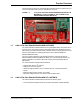


Table Of Contents

Installation and Operation
2021
Microchip Technology Inc. and its subsidiaries
DS50003218A-page 19
2.2 SPI DEMO
Once the Curiosity board is programmed and running, LED D4 will blink, while the other
LEDs will remain off. This indicates that the SPI DAC is working and the output can be
monitored on Channel 0 of the SPI output. When LED D4 is blinking, Channel 0 will
output a sine wave as shown in the following figure.
FIGURE 2-15: SPI OUTPUT SINE WAVE (LED D4 BLINKING, LEDS D2, D3
AND D5 OFF)
The frequency of the sine wave can be modified by rotating the potentiometer on the
Curiosity board, as shown in the following figure. Rotating the potentiometer will also
change the blink rate of LED D4.
FIGURE 2-16: SPI OUTPUT SINE WAVE WITH VARYING FREQUENCY
USING THE POTENTIOMETER (LED D4 BLINKING, LEDS D2,
D3 AND D5 OFF)