
Datasheet

2010 Microchip Technology Inc. Preliminary DS22266A-page 13
MCP7941X
4.2.3 CALIBRATION
The MCP7941X utilizes digital calibration to correct for
inaccuracies of the input clock source (either external
or crystal). Calibration is enabled by setting the value
of the Calibration register at address 08H. Calibration
is achieved by adding or subtracting a number of input
clock cycles per minute in order to achieve ppm level
adjustments in the internal timing function of the
MCP7941X.
The MSB of the Calibration register is the sign bit, with
a ‘1’ indicating subtraction and a ‘0
’ indicating addition.
The remaining seven bits in the register indicate the
number of input clock cycles (multiplied by two) that
are subtracted or added per minute to the internal
timing function.
The internal timing function can be monitored using
the MFP open-drain output pin by setting bit [6]
(SQWE) and bits [2:0] (RS2, RS1, RS0) of the control
register at address 07H. Note that the MFP output
waveform is disabled when the MCP7941X is running
in V
BAT mode. With the SQWE bit set to ‘1’, there are
two methods that can be used to observe the internal
timing function of the MCP7941X:
A. RS2 BIT SET TO ‘0’
With the RS2 bit set to ‘0’, the RS1 and RS0 bits
enable the following internal timing signals to be
output on the MFP pin:
The frequencies listed in the table presume an input
clock source of exactly 32.768 kHz. In terms of the
equivalent number of input clock cycles, the table
becomes:
With regards to the calibration function, the Calibration
register setting has no impact upon the MFP output
clock signal when bits RS1 and RS0 are set to ‘11’.
The setting of the Calibration register to a non-zero
value (i.e., values other than 00H or 80H) enables the
calibration function which can be observed on the
MFP output pin. The calibration function can be
expressed in terms of the number of input clock cycles
added/subtracted from the internal timing function.
With bits RS1 and RS0 set to ‘00’, the calibration
function can be expressed as:
Since the calibration is done once per minute (i.e.,
when the internal minute counter is incremented), only
one cycle in sixty of the MFP output waveform is
affected by the calibration setting. Also note that the
duty cycle of the MFP output waveform will not
necessarily be at 50% when the calibration setting is
applied.
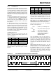
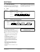
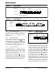
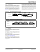
With bits RS1 and RS0 set to ‘01’ or ‘10’, the
calibration function can not be expressed in terms of
the input clock period. In the case where the MSB of
the Calibration register is set to ‘0’, the waveform
appearing at the MFP output pin will be “delayed”,
once per minute, by twice the number of input clock
cycles defined in the Calibration register. The MFP
waveform will appear as:
FIGURE 4-1: RS1 AND RS0 WITH AND WITHOUT CALIBRATION
RS2 RS1 RS0 Output Signal
000 1 Hz
001 4.096 kHz
010 8.192 kHz
011 32.768 kHz
RS2 RS1 RS0 Output Signal
000 32768
001 8
010 4
011 1
T
output
= (32768 +/- (2 * CALREG)) T
input
where:
T
output
= clock period of MFP output signal
T
input
= clock period of input signal
CALREG = decimal value of Calibration
register setting and the sign is
determined by the MSB of
Calibration register.
Delay