
Datasheet


Micrel Inc. MIC4451/4452
October 2011 9
M9999-103111-B
MIC4451
1
8
6, 7
5
4
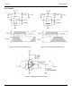
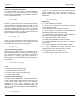
+18
0.1µF
0.1µF
TEK CURRENT
PROBE 6302
2,500 pF
POLYCARBONATE
5.0V
0 V
18 V
0 V
300 mV
12 AMPS
PC TRACE RESISTANCE = 0.05
LOGIC
GROUND
POWER
GROUND
WIMA
MKS-2
1µF
Figure 4. Switching Time Degradation Due to Negative
Feedback
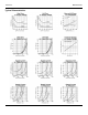
The supply current vs. frequency and supply current vs
capacitive load characteristic curves aid in determining
power dissipation calculations. Table 1 lists the
maximum safe operating frequency for several power
supply voltages when driving a 10,000pF load. More
accurate power dissipation figures can be obtained by
summing the three dissipation sources.
Given the power dissipation in the device, and the
thermal resistance of the package, junction operating
temperature for any ambient is easy to calculate. For
example, the thermal resistance of the 8-pin plastic DIP
package, from the data sheet, is 130°C/W. In a 25°C
ambient, then, using a maximum junction temperature of
125°C, this package will dissipate 960mW.
Accurate power dissipation numbers can be obtained by
summing the three sources of power dissipation in the
device:
• Load Power Dissipation (P
L
)
• Quiescent power dissipation (P
Q
)
• Transition power dissipation (P
T
)
Calculation of load power dissipation differs depending
on whether the load is capacitive, resistive or inductive.
Resistive Load Power Dissipation
Dissipation caused by a resistive load can be calculated
as:
P
L
= I
2
R
O
D
where:
I = the current drawn by the load
R
O
= the output resistance of the driver when the output
is high, at the power supply voltage used. (See data
sheet)
D = fraction of time the load is conducting (duty cycle)
Capacitive Load Power Dissipation
Dissipation caused by a capacitive load is simply the
energy placed in, or removed from, the load capacitance
by the driver. The energy stored in a capacitor is
described by the equation:
E = 1/2 C V
2
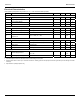
VS Max. Frequency
18V 220kHz
15V 300kHz
10V 640kHz
5V 2MHz
Table 1: MIC4451 Maximum Operating Frequency
As this energy is lost in the driver each time the load is
charged or discharged, for power dissipation calculations
the 1/2 is removed. This equation also shows that it is
good practice not to place more voltage on the capacitor
than is necessary, as dissipation increases as the
square of the voltage applied to the capacitor. For a
driver with a capacitive load:
P
L
= f C (V
S
)
2
where:
f = Operating Frequency
C = Load Capacitance
V
S
= Driver Supply Voltage