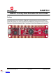
SAM D21 SAM D21 Curiosity Nano Evaluation Kit User's Guide Preface The SAM D21 Curiosity Nano Evaluation Kit (DM320119) is a hardware platform to evaluate the SAMD21G17D ® microcontroller (MCU), and it is supported by the MPLAB X Integrated Development Environment (IDE). The evaluation kit provides an easy access to the features of the SAMD21G17D to integrate the device into a custom design.
SAM D21 Table of Contents Preface........................................................................................................................................................... 1 1. Introduction............................................................................................................................................. 3 1.1. 2. Getting Started........................................................................................................................................
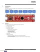
SAM D21 Introduction 1. Introduction Kit Overview The SAM D21 Curiosity Nano evaluation kit is a hardware platform used to evaluate the SAMD21G17D MCU. Figure 1-1. Kit Overview 1.
SAM D21 Getting Started 2. Getting Started 2.1 Curiosity Nano Quick Start Follow these steps to explore the Curiosity Nano platform: 1. 2. 3. Download MPLAB X IDE. Launch MPLAB X IDE. Connect a USB cable (Standard-A to Micro-B or Micro-AB) between the PC and the debug USB port on the kit. When the Curiosity Nano kit is connected to the computer for the first time, the operating system will perform a driver ® ® software installation.
SAM D21 Curiosity Nano 3. Curiosity Nano 3.1 On-Board Nano Debugger Curiosity Nano is an evaluation platform that provides a set of small boards with access to most of the microcontroller I/Os. The platform consists of a series of low pin-count microcontroller (MCU) boards, which are integrated with MPLAB X IDE to present relevant user guides, application notes, data sheets, and example codes.
SAM D21 Curiosity Nano • 3.1.1.3 Stop bits: One or two bits are supported. Signaling During USB enumeration, the host OS will start both communication and data pipes of the CDC interface. At this point, it is possible to set and read baud rate and other UART parameters of the CDC, but data sending and receiving will not be enabled. When a terminal connects on the host, it must assert the DTR signal.
SAM D21 Curiosity Nano ...........continued Debugger Signal ICSP Target Description VTG - Target voltage GND - Common ground. DBG0 SWDATA Debug data line. DBG3 nRESET Reset line VOFF - Voltage Off input. VBUS - VBUS voltage for external use. Figure 3-1. Curiosity Nano Standard Pinout 3.3 Power Supply The evaluation kit is powered through the USB port and contains two regulators for generating 3.3V for the debugger and an adjustable regulator for the target.
SAM D21 Curiosity Nano 3.3.1 Target Voltage Regulator The target voltage regulator is a MIC5353 variable output LDO. The On-Board Nano Debugger can adjust the voltage output that is supplied to the kit target section by manipulating the MIC5353's feedback voltage. The hardware implementation is limited to an approximate voltage range from 1.7V-5.1V.
SAM D21 Curiosity Nano 3.4 Disconnecting the On-Board Nano Debugger The following block diagram shows connections between the debugger and the SAMD21G17D microcontroller. The round boxes represent connections to the board edge on the SAM D21 Curiosity Nano. The signal names are shown in Figure 3-1 and printed in silkscreen on the bottom side of the board. Figure 3-4.
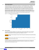
SAM D21 Curiosity Nano 3.5 Current Measurement The power to the SAMD21G17D is connected from the on-board power supply to the target voltage supply (VTG) with a cut strap as shown in Disconnecting the On-Board Debugger. To measure the power consumption of the SAMD21G17D and other peripherals connected to the board, cut the strap and connect an ammeter over the strap. The ammeter can be connected between the target VTG pad edge connector and an external power supply for easy measurement.
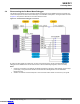
SAM D21 Hardware 4. Hardware 4.1 Connectors 4.1.1 SAM D21 Curiosity Nano Pinout All of the SAM D21G17D I/O pins are accessible at the edge connectors on the SAM D21 Curiosity Nano, except the button and LED (PB10, PB11). The following figure shows the evaluation kit pinout. RA30 and RA31 are only available at the edge connector in the debugger section as long as the cut straps on the bottom are not cut.
© 2020 Microchip Technology Inc. Downloaded from Arrow.com.
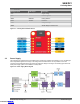
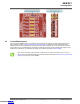
© 2020 Microchip Technology Inc. Downloaded from Arrow.com. Curiosity Nano Base for click boards TM PA02 AN PWM PB09 PB08 AN PWM PA05 PA07 RST INT PA06 PB23 RST INT PA23 PA18 CS RX PA09 PA28 CS RX PA09 PA17 SCK TX PA08 PA17 SCK TX PA08 PA19 MISO SCL PA13 PA19 MISO SCL PA13 SDA PA12 PA16 MOSI SDA PA12 +5V +5V +3.3V +3.3V +5V +5V GND GND GND GND GND GND PA16 MOSI +3.3V +3.
SAM D21 Hardware 4.2 4.2.1 Peripherals LED One yellow LED is available on the SAM D21 Curiosity Nano evaluation kit, which can be controlled either with a GPIO or PWM. The LED can be activated by driving the connected I/O line to the GND. Table 4-1. LED Connection SAMD21G17D PB10 4.2.2 Function Shared Functionality Yellow LED0 None Mechanical Switch The SAM D21 Curiosity Nano has one mechanical switch, a generic user configurable switch.
SAM D21 Hardware ...........continued SAMD21G17D pin Debugger pin Function Shared Functionality PA31 DBG0 SWDATA Edge Connector PA30 DBG1 SWCLK Edge Connector PB11 DBG2 GPIO Edge Connector and SW0 nRESET DBG3 nRESET Edge Connector VCC_LEVEL 1.7V-3.6V supply voltage Edge Connector GND Common ground Edge Connector VCC_TARGET GND © 2020 Microchip Technology Inc. Downloaded from Arrow.com.
SAM D21 Hardware Revision History 5. 5.1 Hardware Revision History This user guide provides the latest available revision of the kit. This chapter contains information about known issues, a revision history of older revisions, and how older revisions differ from the latest revision. Identifying Product ID and Revision The revision and product identifier of Curiosity Nano boards can be found in two ways; either through the MPLAB X IDE or by looking at the sticker on the bottom of the PCB.
SAM D21 Schematics 6. Schematics Figure 6-1. Target Microcontroller (SAMD21G17D) U_SAMD21_Curiosity_Nano_Debugger R3 SAMD21_Curiosity_Nano_Debugger R3.SchDoc U_SAMD21_Curiosity_Nano_Target_MCU R3 SAMD21_Curiosity_Nano_Target_MCU R3.SchDoc ID_SYS VOFF ID_SYS VOFF CDC_UART CDC_UART DBG0 DBG1 DBG2 DBG3 DBG0 DBG1 DBG2 DBG3 © 2020 Microchip Technology Inc. Downloaded from Arrow.com.
rotatethispage90 DEBUGGER CONNECTIONS CDC_UART _ SAMD21 (Target Device) C207 GND C208 UART RX TX DBG0 DBG3 DBG1 DBG2 VOFF ID_SYS 100n VCC_TARGET 1u PROG/DEBUG Pull VCC_TARGET R204 PA28 nRESET PA27 PB23 PB22_CDC5_RX R205 47k 47k DBG0 DBG1 nRESET Pull VCC_TARGET GND C201 100n PB08_ADC2 PB09_PWM3 PA04_PWM4 PA05_ADC5 PA06_ADC6 PA07_ADC7 L200 BLM18PG471SN1 VCC_TARGET VDDIO GND USB_DP/PA25 USB_DM/PA24 USB_SOF/PA23 PA22 PA21 PA20 PA19 PA18 PA17 PA16 36 35 34 33 32 31 30 29 28 27 26 25 PA25
rotatethispage90 TARGET ADJUSTABLE REGULATOR VIN VCC_REGULATOR MIC5353 4 VOUT EN NC/ADJ VCC_EDGE J101 MIC94163 GND 2.2uF GND CDC TX J100 VCC_TARGET MIC5353: Vin: 2.6V to 6V Vout: 1.25V to 5.1V Imax: 500mA Dropout (typical): 50mV@150mA, 160mV @ 500mA Accuracy: 2% initial Thermal shutdown and current limit SWD TARGET UART RX CDC RX UART TX DBG0 SWDAT DBG1 SWCLK DBG2 GPIO DBG3 nRESET VCC 3.
SAM D21 Document Revision History 7. Document Revision History Rev C - 07/2020 Updated the figures in the following section, and added a note: • SAMD21G17D Curiosity Nano Pinout Added a new section: • SAMD21G17D Curiosity Nano Base Quick Reference Rev B - 04/2020 Updated the pin names for the SAMD21G17D in the Connection Details between the Target and Debugger Section Table. Rev A - 12/2019 This is the initial released version of this document. © 2020 Microchip Technology Inc. Downloaded from Arrow.com.
SAM D21 The Microchip Website Microchip provides online support via our website at www.microchip.com/. This website is used to make files and information easily available to customers.
SAM D21 your specifications. MICROCHIP MAKES NO REPRESENTATIONS OR WARRANTIES OF ANY KIND WHETHER EXPRESS OR IMPLIED, WRITTEN OR ORAL, STATUTORY OR OTHERWISE, RELATED TO THE INFORMATION, INCLUDING BUT NOT LIMITED TO ITS CONDITION, QUALITY, PERFORMANCE, MERCHANTABILITY OR FITNESS FOR PURPOSE. Microchip disclaims all liability arising from this information and its use.
Worldwide Sales and Service AMERICAS ASIA/PACIFIC ASIA/PACIFIC EUROPE Corporate Office 2355 West Chandler Blvd. Chandler, AZ 85224-6199 Tel: 480-792-7200 Fax: 480-792-7277 Technical Support: www.microchip.com/support Web Address: www.microchip.