
User Guide

4.2 Peripherals
4.2.1 LED
One yellow LED is available on the SAM D21 Curiosity Nano evaluation kit, which can be controlled either with a
GPIO or PWM. The LED can be activated by driving the connected I/O line to the GND.
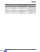
Table 4-1. LED Connection
SAMD21G17D Function Shared Functionality
PB10 Yellow LED0 None
4.2.2 Mechanical Switch
The SAM D21 Curiosity Nano has one mechanical switch, a generic user configurable switch. When this switch is
pressed, it will drive the I/O line to ground (GND).
Note: No pull-up resistor is connected to the generic user switch. Ensure that the internal pull-up is enabled in the
SAMD21G17D to use the switch.
Table 4-2. Mechanical Switch
SAMD21G17D Function Shared Functionality
PB11 User switch SW0 DBG2 and Edge connector
4.2.3 Crystal
The SAM D21 Curiosity Nano board has the option for a 32.768 kHz crystal, and by default this crystal is not
connected to the SAMD21G17D, as GPIOs are routed out to the edge connector. To use the crystal, some hardware
modifications are required. The two I/O lines routed to the edge connector must be disconnected to reduce the
chance of contention to the crystal, and to remove excessive capacitance on the lines.
Table 4-3. Crystal Connections
SAMD21G17D pin Function Shared Functionality
PA00 XIN32 Edge connector
PA01 XOUT32 Edge connector
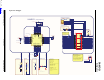
4.3 On-Board Nano Debugger Implementation
The SAM D21 Curiosity Nano features an On-Board Nano Debugger that can be used to program and debug the
SAMD21G17D using a Serial wire debug (SWD). The On-Board Nano Debugger also includes a Virtual Com port
interface over UART and DGI GPIO. MPLAB X IDE can be used as a front-end for the On-Board Nano Debugger for
programming and debugging. Data Visualizer can be used as a front-end for the CDC and DGI GPIO.
4.3.1 On-Board Nano Debugger Connections
The following table provides the connection details between the target and the debugger section. All connections
between the target and the debugger are tri-stated as long as the debugger is not actively using the interface,
therefore little contamination of the signals and the pins can be configured to the application requirements. For
additional information on how to use the capabilities of the On-Board Nano Debugger, see
Curiosity Nano.
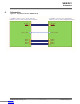
Table 4-4. Connection Details between the Target and Debugger Section
SAMD21G17D pin Debugger pin Function Shared Functionality
PB22 CDC TX UART TX (SAMD21G17D RX line) Edge Connector
PA22 CDC RX UART RX (SAMD21G17D TX line Edge Connector
SAM D21
Hardware
© 2020 Microchip Technology Inc.
User Guide
DS70005409C-page 14
Downloaded from Arrow.com.Downloaded from Arrow.com.Downloaded from Arrow.com.Downloaded from Arrow.com.Downloaded from Arrow.com.Downloaded from Arrow.com.Downloaded from Arrow.com.Downloaded from Arrow.com.Downloaded from Arrow.com.Downloaded from Arrow.com.Downloaded from Arrow.com.Downloaded from Arrow.com.Downloaded from Arrow.com.Downloaded from Arrow.com.