Microcom AD 2730 (2735) ADSL 2/2+ WiFi router User Guide
Microcom AD 2730, AD 2735 User’s Guide Table of Contents Preliminary Pages Page 1.1 Introduction............................................................................................. 1-8 1.2 Scope and Purpose................................................................................ 1-8 1.3 Targeted Audience ................................................................................. 1-8 1.4 Manual Organisation .......................................................................
5.6.14 System Password................................................................................. 5-30 5.6.15 Firmware Upgrade................................................................................ 5-31 5.6.16 Restore to Default ................................................................................ 5-32 5.7 Security................................................................................................. 5-32 5.7.1 IP Filters .........................................
List of Illustrations Figure Page Figure 1-1 : Wireless-G System Configuration Diagram ................................................................. 2-9 Figure 1-2 : Wireless Router Connection Diagram ....................................................................... 4-13 Figure 1-3 : Setup Page ................................................................................................................ 5-14 Figure 1-4 : Basic Home Screen .......................................................
Figure 1-28 : Routing Table........................................................................................................... 5-30 Figure 1-29 : System Password .................................................................................................... 5-31 Figure 1-30 : Firmware Upgrade ................................................................................................... 5-31 Figure 1-31 : Restore to Default prompt.............................................................
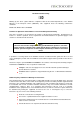
Declaration Of Conformity Marking by the above symbol indicates compliance with the Essential Requirements of the R&TTE Directive of the European Union (1999/5/EC). This equipment meets the following conformance standards: EN300 328, EN301 489-17, EN60950 Countries of Operation and Conditions of Use in the European Community This device is intends to be operated in all countries of the European Community. Requirement is for indoors vs.
Modifications made to the product, unless expressly approved by the party responsible, could void the user’s right to operate the equipment. RF Exposure This device has been tested and complies with FCC RF Exposure (SAR) limits in typical laptop computer configurations and this device can be used in desktop or laptop computers with side mounted PCMCIA slots, which can provide 1 cm separation distance from the antenna to the body of the user or a nearby person.
Chapter 1 - About this Manual 1.1 Introduction This manual provides a general product overview and description of its subsystems and components and basic operation and preventive maintenance instructions of the ADSL 2/2+ Ready Wireless LAN 802.11g 4 Port Ethernet & USB Combo Router. 1.
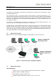
Chapter 2 – ADSL Router Description The ADSL 2/2+ Ready Wireless LAN 802.11g 4 Port Ethernet & USB Combo 4 Port Router is a highspeed WAN bridge/router. This full-featured product is specifically designed allow maximum of 4 Ethernet-workstations to be connected to the Internet and directly connect to your local area network via high speed 10/100 Mbps Ethernet. Users using wireless workstations will be able to connect to the Internet using 802.11g wireless technology.
• Bridge Tap Mitigation support • ATM Layer with Traffic shaping QoS Support (UBR, CBR, VBR-rt, VBR-nrt) • AAL ATM Attributes - AAL5 • Multiple PVC up to 8 support (Bridge Support) • Spectral compatibility with POTS • F5 OAM Loopback/Send and Receive Encapsulation Support • RFC2684 Bridge and Routed LLC and VC Mux support • RFC2364 PPPoA Client support • RFC2516 PPPoE Client support • RFC2225/RFC1577 Classical IP Support • Transparent Bridge Support • PAP/CHAP/MS-CHAP for Password Authentication Support N
• Web Based Firmware Upgrade (Local) • Soft Factory Reset Button via Web GUI • Diagnostic Test (DSL, OAM, Network, Ping Test) • Telnet/CLI (Read Only) • Syslog Support • Firmware upgrade-able for future feature enhancement Security Support • NAT for basic Firewall support • Packet Filtering Firewall Support • Stateful Packet Inspection Support • Protection against Denial of Service attacks • Password Authentication to Modem External Connectors: • 1 x RJ-11 Telephone socket for ADSL line • 4 x RJ45 for 10/
Chapter 3 - Your Gateway At A Glance The ADSL Ethernet & USB Combo may have different ports and LEDs. Let’s take a look at the different options. Depending on your model, it may have some or all of the features listed below 3.1 Ports and Buttons Reset and Restore to Factory Defaults: The restore to factory defaults feature will set the ADSL Router to its factory default configuration by resetting the ADSL Router.
Chapter 4 - Installing The ADSL Router 1. Locate a suitable location for the ADSL Router. For connections to the Ethernet and DSL interfaces, please refer to the easy start guide. 2. Connect the AC Power Adapter. Depending upon the type of network, you may want to put the power supply on an uninterruptible supply (UPS). Note… Only use the power adapter supplied with the ADSL Router. A different adapter may damage the product. Fig 1-2 shows the Wireless 4-port Router connection diagram.
Chapter 5 - Setting Up the ADSL Router (Basic Mode) The basic tabs consist of features which are catered for basic users. This section will guide you through your ADSL Router’s configuration. The ADSL Router is shipped with a standard PPP configuration.. 5.1 Logging into your ADSL Router To configure your ADSL Router, open your web browser. You may get an error message at this point; this is normal. 1. Type the default IP address (192.168.1.1) or login.router on on the web address bar. 2.
Figure 1-4 : Basic Home Screen 5.2 Quick Start By default the ADSL Router has being configured to PPP connection and user is only required to enter the username and password (as specified by the local ISP) to connect to the Internet. The Quick Start page is meant for basic users whom only require easy connectivity to the Internet without worrying about any other advance configuration setting.
5.3 LAN / DHCP Configuration On one side of your ADSL Router, you have your own Local Area network (LAN) connections. This is where you plug in your local computers to the ADSL Router. The ADSL Router is normally configured to automatically provide all the PC's on your network with Internet addresses. To enable or disable DHCP, Click setup. Under LAN Setup, select DHCP Configuration. This will bring up the screen shown in Fig 1-5-1.
5.4 Diagnostic Test Diagnostic Test is used for investigating whether the ADSL Router is properly connected to the WAN Network. See Fig 1-6. This test may take a few seconds to complete. To perform the test, select your connection from the list and press the Test button. Before running this test, make sure you have a valid DSL link. Figure 1-6 : Diagnostics Test Screen After running the Diagnostic Test, the screen will indicate that the portion which pass or fail the test.
Figure 1-8 : Ping Test Screen 5.5 Wireless 5.5.1 Wireless Setup The SSID default which is defaulted as “yournetworkname” can be changed. SSID is wireless network name for the wireless router, your wireless client will need this name for wireless connection. The wireless setup allows the user to enable or disable the AP (access point for the wireless feature). Disabling of A.P will prevent the wireless router from emitting any wireless signal.
5.5.2 Wireless Configuration For users who want to explore the advanced features, you can click on the Advance button. The options listed can be changed to cater for advance users. See Fig 1-10 Figure 1-10 : Wireless Configuration Page 5.5.3 Wireless Security It is important for user to enforce security in wireless LAN environment, this is to prevent unauthorized wireless users from accessing your router. By default, the ‘None’ radio button is selected.
In order to implement security, proceed with the following steps. See Fig 1-12 1. Select the WEP option. 2. Check on “Enable WEP Wireless Security” option. 3. Select the “Cipher”option, the available options are 64 bits, 128 bits and 256 bits. 4. You can configure up to 4 sets of keys for your wireless client. Figure 1-12: Wireless Security settings Enter the IP Address of the RADIUS Server (for 802.1x authentication purposes).
WPA which stands for WiFi Protected Access. WPA is an industry-supported, pre-standard version of 802.11i utilizing the Temporal Key Integrity Protocol (TKIP), which fixes the problems of WEP, including using dynamic keys. Figure 1-14 : Wireless Security 5.5.4 Wireless Management Wireless Management consists of Aceess List, Associated Stations and Multiple SSID. 5.5.4.1 Access List This feature permits you to “Allow” or “Ban” any wireless client from accessing the wireless router.
5.6 Advanced This mode is catered for advance users, a brief explanation of the links are listed as shown below. Figure 1-16 : Advance Screen 5.6.1 WAN Connection On the other side of the ADSL Router is where your Wide Area Network (WAN) connection; also referred to as a broadband connection. This WAN connection is different for every WAN supplier. Most of the configuration you will perform will be in this area. Local Area Network Connection(s) 5.6.
Figure 1-17 : New Connection (PPPOE Connection Setup) 5.6.3 ADSL Modulation To configure the DSL modulation type, Click setup. Under WAN Setup, select Modem Setup. This will bring up the modem setup screen. Leave the default value if you are unsure or the DSL/ISP did not provide this information. For most all cases, this screen should not be modified. Figure 1-18 : ADSL Modulation (Modem Setup) 5.6.4 Quickstart PPPoE is also known as RFC 2516.
To configure the gateway for PPPoE, click on Setup and then click on New Connection. The default PPPoE connection setup is displayed. At the Type field select PPPoE and the PPPoE connection setup page is displayed. Give your PPPoE connection a unique name; the name must not have spaces and cannot begin with numbers. In this case the unique name is called PPPoE1. Select the encapsulation type (LLC or VC); if you are not sure just use the default mode.
5.6.5 LAN Configuration You can change the ADSL Router’s IP address by, clicking Setup and under LAN Setup, select LAN Configuration, then click Configure. Your ADSL Router’s default IP address and subnet mask are 192.168.1.1/255.255.255.0; this subnet mask will allow the ADSL Router to support 254 users. If you want to support a larger number of users you can change the subnet mask; but remember. The DHCP server is defaulted to only give out 255 IP addresses.
Figure 1-21 : LAN Clients 5.6.7 Ethernet Switch Configuration The IGMP Snooping prevents the switch from flooding the LAN ports with multicast frames, and will instead direct them to the CPU port for processing. Users are able to specify connection speed and set their values accordingly from the following available options.
5.6.8 Application (UPnP) UPnP NAT and Firewall Traversal allow traffic to pass-thru the ADSL Router for applications using the UPnP protocol. This feature requires one active DSL connection. In presence of multiple DSL connections, select the one over, which the incoming traffic will be present, for example the default Internet connection. To enable UPnP, you must first have a WAN connection configured. Once a WAN connection is configured, click Advanced and under Advanced, select UPnP.
8. Time Zone - The time zone of the router. 9. Day Light - Check/uncheck this option to enable/disable day light saving. See Fig 1-24 Figure 1-24 : SNTP 5.6.10 SNMP SNMP (Simple Network Management Protocol) is a troubleshooting and management protocol, which uses the UDP protocol on port 161 to communicate between clients and servers. SNMP uses a manager MIB (management information base) agent solution to fulfill the network management needs.
5.6.11 Routing (Static Routing) If the ADSL Router is connected to more than one network, you may need to set up a static route between them. A static route is a pre-defined pathway that network information must travel to reach a specific host or network. You can use static routing to allow different IP domain users to access the Internet through the ADSL Router. The New Destination IP is the address of the remote LAN network or host to which you want to assign a static route.
See Fig 1-27 Figure 1-27 : Dynamic Routing 5.6.13 Routing Table Routing Table shows the information used by routers when making packet forwarding decisions. Packets are routed according to the packet's destination IP address. Figure 1-28 : Routing Table 5.6.14 System Password You can change your ADSL Router’s username and password by clicking on User Management. From here you can change the login name and password.
Figure 1-29 : System Password 5.6.15 Firmware Upgrade You can upgrade the ADSL Router’s firmware, clicking on Update Gateway under the Tools page. To upgrade the firmware, click browse, find the firmware file to download. Make sure this is the correct file. Click on upgrade firmware. Once the upgrade is complete the ADSL Router will reboot. You will need to log back onto the ADSL Router after the firmware upgrade is completed. The firmware upgrade should take about 5 minutes to complete.
5.6.16 Restore to Default The restore to factory defaults feature will set the ADSL Router to its factory default configuration by resetting the ADSL Router. You may need to place the ADSL Router into its factory defaults if the configuration is changed, you loose the ability to interface to the ADSL Router via the web interface, or following a software upgrade,. To reset the ADSL Router, simply press the reset button for about ~ 10 seconds.
Figure 1-33 : IP Filters 5.7.2 LAN Isolation LAN isolation allows you to disable the flow of packets between up to three-user-defined LAN groups (WLAN, USB, and Ethernet). This allows you to secure information in private portions of the LAN from other, publicly accessible LAN segments. Figure 1-34 : LAN Isolation 5.7.3 URL Filter This feature allows the router to block access to certain websites by examining its URL, a text string describing a unique location on the Internet.
Figure 1-35 : URL Filters 5.
5.8.1 Connection Status Connection Status will display all the relevant information regarding your Internet Connection, it will display the type of protocol used, the WAN IP address, the connection state and the duration will be displayed. See Fig 1-37 Figure 1-37 : Connection Status 5.8.2 System Log You can display the ADSL Router’s log by going under the Status title, click System log. From here you can view all logged information.
5.8.3 Remote Log Settings This feature is for users to enable remote logging. Settings mentioned below are essential for this feature to work: • Log Level • Adding / Deleting IP address • Logging destination Figure 1-39 : Remote Log Settings 5.8.4 Network Statistics Information regarding the Status and Statistics of your Ethernet, USB and DSL line will be displayed. Figure 1-40 : Network Statistics 5.8.5 DHCP Clients Shows the users connected.
Figure 1-41 : DHCP Clients 5.8.6 Modem Status This screen will display the Modem status and DSL statistics. Figure 1-42 : Modem Status 5.8.7 Product Information This screen will show a summary of all the product information and software version that comes bundled with the ADSL router.
Figure 1-43 : Product Information 5.9 Help The Help screen takes you to the different Help Sections for Firewall, Bridge Filters, LAN Clients, LAN Group Configurations, PPP Connection, UPnP, IP QoS and RIP Help.