G1100 WirelessHART Smart Gateway User Manual V2.
http://www.microcyber.cn WirelessHART Smart Gateway G1100 Caution In order to ensure the personal and property safety, and get the best product experience, before using, installation, and maintenance products, please be sure to read all the content of the document. Security Reminder The user must pay special attention to the content of this manual to ensure that the personal and property safety. The potential security problems may cause are marked with orange color.
http://www.microcyber.cn 1 2 3 4 5 6 Overview ................................................................................................................................... 1 1.1 Brief Introduction ................................................................................................................ 1 1.2 Including Goods .................................................................................................................. 1 First Connection ..................................
http://www.microcyber.cn 7 6.3 Statistics Information ........................................................................................................ 39 6.3.1 Network Statistics .................................................................................................. 39 6.3.2 Modbus Statistics ................................................................................................... 40 6.4 Setting ..................................................................................
http://www.microcyber.
http://www.microcyber.cn 1 Overview Warning Please pay attention to the rules, otherwise it may cause damages to personal and property. Please ensure the installation is carried out by the expertise staff. Please ensure the working environment and related danger lever are relevant. 1.
http://www.microcyber.cn 2 First Connection Note All webpage screenshots, involved in this chapter, derive from Chinese page of gateway webpage. Warning Please pay attention to the installation rules, otherwise it may cause death or severe injury. Please ensure the installation is only carried out by expertise staff. The explosion may cause death or severe injury. Please check the equipment s working environment and related dangerous environment certification are relevant.
http://www.microcyber.cn 2.2 System Requirements There are the requirements for PC/portable computer, when to configure the gateway: Network browser application program (support one of them) Firefox browser 35 or plus Chrome browser 40 or plus Microsoft Internet Explorer 8.0 or plus Ethernet 10/100base-TX Ethernet communication protocol 2.3 First Setting 2.3.1 Prepare PC/Portable Computer The user shall configure PC/portable computer before gateway communication, to establish a private network.
http://www.microcyber.cn 5) 6) 7) 8) Choose Use the following IP address from General . Set IP address as 192.168.2.XX (and it cannot be as the same as gateway, gateway default IP is 192.168.2.253), and press Tab. Subnet mask shall be set as 255.255.255.0. Click OK , close Internet Protocol (TCP/IP) and Local Area Connection . 2.3.
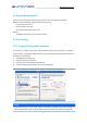
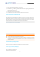
http://www.microcyber.cn 2)Input in the address bar: https://192.168.2.253. 3)Confirm the security, and then continue. 4)Input username admin. 5)Input password 123456. Now the network browser has been in the gateway s default homepage, the left side of homepage is navigation menu, including: Network information: Check WirelessHART network status, online device information and measurement information.
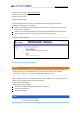
http://www.microcyber.cn 10.0.0.0~10.255.255.254. IP address 192.168.99.xxsegment is not available. 3)Click Submit . 4)If the reminder is Successful! , click Yes . If the reminder is Failed , the user shall resubmit and check the gateway s Ethernet connection. Please refer to Section 5. 5)If the reminder is Restart gateway now? , click Yes . The gateway shall restart. 6)Restart network browser.
http://www.microcyber.cn 5) Click Restart , to restart the gateway and the setting is effective.
http://www.microcyber.cn 3 Installation and Connection Warning Explosion may cause death or severe injury. Please check if the device working environment is related to relevant dangerous place certification. Electrostatic discharge may damage electric devices: Before taking the electric devices, or connecting leads or terminals, the people-ground device shall be set. Electricity shock may cause death or severe injury.
http://www.microcyber.cn inches) high from the ground or 2m (6 inches) high from the base facility. Figure 3-1 is an example for that. Figure 3-1 Gateway Installation The gateway shall be fixed to the designed position with the pendant, and the pendant is provided together with the gateway. The hole dimension of gateway bottom housing and pendant are shown as Figure 3-2, Figure 3-3, Figure 3-4. The steps to install gateway as following: 1) With screw, to fix pendant to the designed position.
http://www.microcyber.cn Figure 3-3 Gateway Bottom Housing Dimension (Unit: mm) Figure 3-4 Gateway Pendant Dimension (Unit: mm) 3.3 Remote Antenna (optional) Remote antenna options provide many optional ways for wireless connection, lightning protection and installation. Warning When installing remote antenna of smart wireless gateway, please obey safety procedure, to avoid falling or touching high voltage cable.
http://www.microcyber.cn Optimal location shall be selected for antenna during installation. Usually, the location is 4.6-7.6m from ground, or more than 2m above the nearest barrier. Installation of EA2 options (outdoor application): 1) Fix antenna onto 2.5cm-5cm diameter rod with attachment. 2) Install arrester onto the top of gateway directly. 3) Use cable to connect grounding shim on top of arrester to reliable grounding. 4) Use the attached coaxial cable to connect antenna with arrester.
http://www.microcyber.cn Use the attached coaxial cable to connect antenna with arrester. Ensure drip loop no less than 0.3m from the arrester. 5) Use the attached coaxial cable to connect gateway with arrester. 6) Use thread sealant to firmly connect wireless gateway, arrester, cable and antenna. 7) Excess length cable shall be curled into 0.3m coil.
http://www.microcyber.cn Table 3-1 Remote Antenna Suite Option Suite Option Antenna Cable 1 Cable 2 Arrester EA2 +6dB gain 12m N/A Male-female connector 0.5dB insertion loss EA3 +6dB gain 9m 3m Female-female connector 0.5dB insertion loss 3.4 Connection All the connections to gateway may be at the wiring terminals, the wiring terminal is inside the housing, and the wiring terminal label is inside the external housing. The standard wiring terminal label is shown in Figure 3-7.
http://www.microcyber.cn the mark as following: 3.4.2 Ethernet The gateway has a 10/100Based-TXEthernet communication port (shown as Figure 2-3). The connection is for access to gateway webpage and pass Modbus TCP HART-IP OPC and own protocol communication. For Ethernet connection, the user shall use Cat 5E type shield cable to connect Ethernet concentrator, interchanger or router. The maximum length of cable is no more than 100m (328 inches). 3.3.
http://www.microcyber.cn power terminal (Figure 3-7). The wiring shall be near gateway, and using external power cut-off switch and breaker. Caution UPS is recommended, to ensure the availability during outage period.
http://www.microcyber.cn 4 PC Integration Note All webpage screenshots, involved in this chapter, derive from Chinese page of gateway webpage. 4.1 Summary The section is about how to connect gateway and PC system, and integrate collected data from field device network, covering network structure, security ability and data mapping. 4.2 Network Structure When the user is determining the network structure and protocol to integrate, the physical connection type is pretty important.
http://www.microcyber.cn connect RS485 bus, the bus is generally connected with serial I/O board or Modbus I/O board. Figure 4-2 RS485 LAN Structure Engineering station Control network Controller and I/O Explosion-proof wirelessHART smart gateway 4.3 Modbus The gateway supports RS485 serial port s Modbus RTU and Modbus TCP based on Ethernet. As a sub-device of Modbus network, polling by Modbus master device or client end (PC system) is requested. 4.3.
http://www.microcyber.cn communication. (none, even check or odd check) Stop bit: The setting determination is used for numbers of stop bit of ModbusRTU communication information end. (1 or 2) TCP Port: It is the TCP/IP port number for Modbus TCP (Ethernet), used by the gateway. The default value is 502. Data format: Modbus communication data format. Support little-endian format, big-endian format.
http://www.microcyber.cn Register starting address: It is the Modbus register number. Modbus register holds 2-byte (16-bit) information, so 32-bit floating value and integer value need 2 Modbus registers. Field device state (HART State) is 1-byte data, and it represents register s high byte, and low byte is not effective. Each data point has the only Modbus register number. Register No.: No. 40001~49000 registers are used for floating value or integer value. No.
http://www.microcyber.cn combine wireless field device s important diagnosis information and communication states. 1: good; 0: bad. Device Variable Code _ HEALTHY parameter is indication of device variable healthy status. These parameters combine important diagnostic information and communication status from wireless field device. 1: good. 0: bad. State is relevant to wireless communication, and marks the device state in wireless network. 1: online 0:off-line.
http://www.microcyber.cn Click Export , and the gateway register map list is saved in terms of CSV file in PC/portable computer.
http://www.microcyber.cn Table 4-4 Own Protocol Format Control Byte Node ID 1Byte Device Status 8Byte 1Byte Extended Device Status 1Byte Command ID 2Byte Number of Byte Payload 1Byte N Byte CRC Parity 2Byte Among them: Control byte: 1 byte bit0 -- 0: Response 1: Request bit1 -- 0: Unicast 1: Broadcast bit2~bit7 : Default value is 0. Node ID: Device long address, 8-byte hexadecimal numbers. Device status: 1 byte, please refer to details in Table 4-2.
http://www.microcyber.cn support command number 0, to read long address of gateway. When long address communicates, format is as below, "00-1B1E-E2-F6-00-09-01", character string is 23. If it is gateway long address, only support command number 160, to read long address of online child device. Transmit Mode 1 Temporarily fixed to 1, cannot exceed 255 Client-side Status 2 Default to "0,0", each number cannot exceed 255 Command Number 1 Transmit command number, range is 0~255.
http://www.microcyber.cn 00-1B-1E-62-F6-00-03-00, 1, 0,0, 180, 10, Device Address+ Transmit Mode+ Client-side Status+Command Number+ Command Load Length 1,2,3,4,5,6,7,8,9,10 Load Received package: 00-1B-1E-62-F6-00-03-00, 0, 0,0, 180, 11, Device Address+ Server Response Code+ Device Status+ Command Number+ Command Load Length 0, HART Reply Code 1,2,3,4,5,6,7,8,9,10 Load 4.5 OPC WirelessHART gateway supports OPC communication protocol.
http://www.microcyber.cn 1) 2) Operate based on hints After installation is completed, pop out the following dialog, OPC server will run automatically. Figure 4-6 OPC Server Automatic Running Interface Usage Usage method of the software is as below: 1. Set Under installation directory, follow pathway "Microcyber\WH_OPCServer\conf" to find fire OPCconfig.
http://www.microcyber.cn Figure 4-8 OPC Server Operation Interface 4.5.2 OPC Mapping OPC mapping is the configuration of wireless field device data points that the OPC server can support for reading by OPC clients. Select "Settings" -> "OPC Mapping" in the gateway webpage to enter the OPC mapping page. Figure 4-9 OPC Mapping page 1. Add a new data point to the OPC mapping table: 1) Click the "Add" button. 2) Fill in all the entries for the new data point.
http://www.microcyber.cn Device ID: The long address of the wireless field device that generated the data. Note: The device ID is not recommended for users to fill in. When the device label is selected, the device ID will be automatically mapped. 3. How to import OPC mapping files: You can configure the OPC mapping of the gateway by importing files. Only CSV files are supported. 1) Click the "Browse..." button to pop up the window for selecting the upload file. 2) Select the CSV file to upload.
http://www.microcyber.cn 5 Failure Solution Caution For more information, please refer to Section 1 in the manual, or get more documentation form Microcyber s website: www.microcyber.cn/en In addition, the contents of the gateway web pages involved in this chapter are all taken from the Chinese pages of the gateway web pages. The section is about basic information for WirelessHART network s failure solution. The user may send email to Microcyber s wireless specialists via specialists. wireless@microcyber.
http://www.microcyber.cn after input the username and password correctly. The default username is admin and the password is 123456. Wireless Field Device 1 Wireless field device is not listed in the device list. 1. Please check if the device is powered correctly, the user may use configuration software/handheld device to check. 2. Check if the device is in the distance available for communication. 3. Check if the wireless device setting parameters are confirmed.
http://www.microcyber.cn 2 Cannot use Modbus TCP communication 1. Check gateway s Modbus TCP terminal port number setting. (The default one is 502.) 2. Check if Modbus master device s IP address is configured correctly, and fill in gateway s IP address correctly, and confirm the gateway and Modbus master are in the same LAN and configured in the same network segment. 3. In Modbus Register Map page, to check if Modbus register map is correct. 3 Receive abnormal Modbus response frame 1.
http://www.microcyber.cn 6 Function Caution For more information, please refer to Section Terms in the manual, or get more documentation form Microcyber s website: www.microcyber.cn/en Warning Following the documentation and related HART specification during the device configuration. With the required engineer s guidance to do configuration. Misconfigured or incorrect time points to configure the device may cause unexpected results.
http://www.microcyber.cn Note Since this manual is a Chinese manual, the following function introductions are based on Chinese pages. The function of the English page is exactly the same as the Chinese page. 6.2 Network Information Caution Each webpage shall refresh at a period time, the updated data shall be marked in green. 6.2.1 Network Overview Choose Network Information > Network Overview . Figure 6-2 Network Overview Number of Nodes Online: Number of online nodes in the present network.
http://www.microcyber.cn Figure 6-3 Node Details HART Tag: Long tag of node. Short Address: Short address distributed by gateway to nodes. Node State: online, offline. Bandwidth status: Indicates that bandwidth is available, Indicates insufficient bandwidth. Join Time: The latest time for the node to join in the network. Joins: The number of node to join in the network. Battery: Only for the inner supportive commands. Caution Click the hyperlink for HART Tag to enter Neighbor Information .
http://www.microcyber.cn Path Stability: Path stability is the stability between node and neighbor nodes. Path Quality: Path quality is the communication quality between node and neighbor node, and the unit is percentage. Path Direction: Path direction s range is valued as upstream or downstream. Link Count: It is the number of link between node and neighbor node. If it is 0, it means there is no path to use. Caution It may display none in the neighbor list and it is normal.
http://www.microcyber.cn Caution Click hyperlink for HART Tag, to enter Burst Setting. There is no hyperlink for offline nodes. Figure 6-6 Burst Setting Node ID: Node s long address, 8-byte hexadecimal number. HART Tag: Long tag of node. Node Type: Device type of node, values are shown as Table 6-1.
http://www.microcyber.cn It shall wait for a while to be effective after Burst Period, Burst Command, Burst Mode, Adapter are modificated. After the modification, it shall show Change in progress... , when the modification items are grey until appear, the modification shall be effective. 6.2.3 Measurement Information Choose Network > Measurement Information . Figure 6-7 Measurement Information HART Tag: Long tag of node. HART State: Display means device online and HART device state is normal.
http://www.microcyber.cn Note Click on the hyperlink of the node tag to access the additional information page. For disconnected nodes, there are no hyperlinks. Figure 6-8 Extra Information Page Node ID: The long address of the node, 8 bytes of hexadecimal number. Node label: The long label of the node. Name: The name of the variable. Value: The value of the variable. Status: Indicates that the variable is normal. Indicates that the variable is abnormal. Updated: update time variable.
http://www.microcyber.cn Node label: The long label of the node. Normally this page only shows the device status. When the Burst command 48 is enabled on the node, this page will display the HART device status, extended device status, standard status 0, standard status 1, standard status 2 and standard status 3. 6.2.4 Failed to join Select "Network Information" -> "Join Failed" to enter the Join Failed page. Figure 6-10 Join Failed Node ID: The long label of the node.
http://www.microcyber.cn 6.2.5 Event Recording Select "Network Info" -> "Event Log" to enter the event log page. Figure 6-11 Event Record Page Click the "View Event Record" button, the page will display various operating information recorded by the system, as shown below: Figure 6-12 Event Logs Tip: Only the user's configuration information for the gateway operation is recorded here. 6.3 Statistics Information Caution The webpage shall real-time refresh, and the updated data shall be marked in green.
http://www.microcyber.cn Figure 6-13 Work Statistics Tx Request: The number of request commands sent by gateway. Tx Request Timeouts: The number of timeout request commands sent by gateway. Rx Response Messages: The number of response commands received by gateway. Tx Request= Tx Request Timeouts+ Rx Response Messages Rx Request: The number of request commands received by gateway. Upstream Packets Lost: Number of Burst package lost. Click the "Reset" button to clear the statistics. 6.3.
http://www.microcyber.cn in the input box. Warning After the complete set on the gateway please do not immediately cut off power, otherwise it will lead to the setup is unable to take effect, resulting in an expected result. 6.4.1 Network Setting Choose Setup > Network . Figure 6-15 Network Network Name: It is defined by customers, and it can be characters, numbers, etc. Network ID: 1~65535 Join Key: It is the security key for starting to join network, 16 bytes, and hexadecimal.
http://www.microcyber.cn Figure 6-16 Node Setting Node Type: Node device type, refer to Table 6-1, read-only. Node ID: Long address of node and it provides the only hexadecimal marked by device. HART Tag: It is used to mark field device and it supports 32 bytes at most. HART Tag supports ISO Latin-1 characters, shown as Table 6-2. Caution HART Tag settings can not be repeated, otherwise it may bring uncertain consequences. Table 6-2 ISO Latin-1 Characters Short Tag: It supports 8-byte length at most.
http://www.microcyber.cn Table 6-3 Packed ASCII Character Delete Delete the offline nodes in the network. Unit range: Click the "Settings" hyperlink to set the PV unit range of the node. Will be described in detail later. Caution For the nodes off the network, HART Tag, Short Tag and Descriptor items in grey cannot be written, and the Delete function is available. Submit: Click Submit to see the following webpage.
http://www.microcyber.cn Figure 6-18 Unit Range Page Node ID: The long address of the node, 8 bytes of hexadecimal number. Node label: The long label of the node. Device Type: The device type of the node. The value is as shown in Table 6-1. 6.4.3 Security Setting Choose Setup > Security . Figure 6-19 Security Setting Click Submit , the web page shall display Restart the Gateway now? click OK. The gateway shall restart, and the setting shall be effective. 6.4.
http://www.microcyber.cn 6.4.5 Protocol Setting Please refer to Communication Setting part in Section 4.3.1 Communication Setting. 6.4.6 Modbus Register Map Please refer to Modbus Register Map part in Section 4.3.2 Register Map. 6.4.7 Time Setting Choose Setup > Time . Figure 6-20 Time Setting The webpage is used to display and set gateway time. Set with PC Time: The gateway time shall be relevant to PC time. Manual entry: The user is admitted to set date (year/month/day) and time (hour/minute/second).
http://www.microcyber.cn Figure 6-21 Firmware Upgrade Page Click the "Select File" button, select the firmware that needs to be updated, click the "Upgrade" button, and the gateway will perform a firmware upgrade and reset automatically. 6.4.10 Backup and restore Choose Settings -> Backup & Restore to go to the Backup & Restore page. Figure 6-22 Backup and Restore Page 1. Save system backup Click the "Save Backup" button and the web page will download the gateway's backup file (.zip file). 2.
http://www.microcyber.cn Click "Restore" and the gateway will perform system restoration and reset automatically. Click the "Restore factory default" button, the gateway system will be restored to the factory default parameters and automatically reset. 6.4.11 About Choose Setup > About . This page is used to display the gateway s terminal block diagram, gateway version and support information.
http://www.microcyber.cn 7 Terms List Term List Description Join Key It is the hexadecimal security code for wireless device to join in wireless network, and the join keys for gateway and device must be same. Device ID Provide the only hexadecimal number of device mark. Network Reliability It is the connection performance for gateway and wireless field device. It is calculated according to the ratio between receiving number of information and estimated number of information.
http://www.microcyber.cn Appendix A Product Specification A.1 Function Specification Input voltage 12~30VDC Current consumption 24V, current < 0.5A Antenna s RF power output Standard antenna: The highest 10dBm (10mW) EIRP Environment Working temperature range: -20~60 (-4~140 ) Working humility range: 10-90% related humility EMC Comply with: GB-T 17626.2-2006 GB-T 17626.4-2008 GB-T 17626.5-2008 Antenna selection The integration of omnidirectional antenna Remote antenna A.
http://www.microcyber.cn HART-IP Support TCP, UDP mode. Supports HART Server software. A.3 Self-assemble Network Specification Protocol IEC 62591 (WirelessHART), 2.4-2.5GHZ DSSS. Largest network scale 250-point wireless device Supported device refresh ratio 1, 2, 4, 8, 16, 32s or 1~60 min Network scale/Delay 250-point device <60s 100-point device <10s 50-point device <5s Data reliability >99% A.
http://www.microcyber.cn A.5 Physical Specification Weight Gateway net weight:3.14kg Gateway + Pendant:3.42kg Size See Figure A- 1. Figure A- 1.
http://www.microcyber.cn Figure A- 2 Explosion-proof Smart Gateway Dimension (Unit: mm) A.6 Ordering Information The standard product is the basic option, if the non-standard product is required, it shall be ordered, and the delivery time shall be checked if the extended product is required.
http://www.microcyber.cn Standard A Standard 24VDC nominal value (12~30VDC) Ethernet connection-physical connection Standard 1 Standard Single Ethernet port Wireless update ratio, working frequency and protocol Standard A3 Standard The update ratio shall be configured by the user, 2.
http://www.microcyber.cn Appendix B Product Certification B.1 FCC and IC The device complies with FCC specification 15. The device shall comply with the following items: The device cannot be interrupted. The antenna and people shall be keep 20cm away with each other during installation. FCC warning: Any Changes or modifications not expressly approved by the party responsible for compliance could void the user's authority to operate the equipment.
http://www.microcyber.cn - IC warning: This device complies with Industry Canada licence-exempt RSS standard(s). Operation is subject to the following two conditions: (1) This device may not cause interference, and (2) This device must accept any interference, including interference that may cause undesired operation of the device. This equipment complies with IC RF radiation exposure limits set forth for an uncontrolled environment.
http://www.microcyber.cn Warning and Caution THIS GATEWAY IS ACCEPTABLE FOR OPERATION IN AMBIENT CONDITIONS NOT EXCEEDING __60__ C (__140__ F); NO SERVICEABLE PARTS OR NO USER SERVICEABLE PARTS. DO NOT OPEN FOR CLEANING.; CAUTION TO REDUCE THE RISK OF IGNITION OF HAZARDOUS ATMOSPHERES, DISCONNECT THE GATEWAY FROM THE SUPPLY CIRCUIT BEFORE OPENING. KEEP TIGHTLY CLOSED WHEN IN OPERATION.
http://www.microcyber.cn installation purpose operation normally. The branch point is 51.4 47.