
User Manual
RFID Reader DEMO Integration User Guide V1.05_02 PAGE: 17
43-RFID INTEGRATION UG105 DATE: 12/13/2006
台揚集團智慧財產
任何未經授權逕予複製、重製、公開或使用本文之行為,將被視為侵害
台揚集團之智慧財產權,將可因此負擔法律責任。
MTI Group Proprietary Information
Any unauthorized use, duplication, reproduction, or disclosure of this document may be
considered as infringement of MTI Group
’s intellectual property rights, the infringer may
be accused and liable applicable legal penalties.
台揚科技股份有限公司
MICROELECTRONICS TECHNOLOGY INC.
ISO 9001 Certified
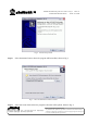
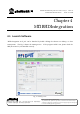
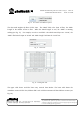
Fig. 11 Connection dialog - TCP Client.
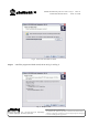
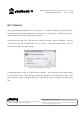
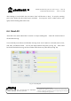
When the socket is connected, the icon of “TCP Connection” will be green as Fig. 12 shows; otherwise
it will be red to indicate the failure of socket connection. The failure is caused by timeout in most of
the cases. Please check the IP address of reader and computer’s setting.
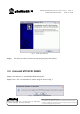
Fig. 12 TCP Connection icon.
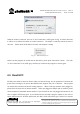
Before exit the program, the socket must be disconnect, please press “Disconnect” button. The color
of “TCP Connection” icon will be gray, and then you could exit the program or connect again.
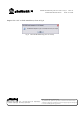
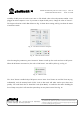
4.3 Read EPC
The RF power must be turned on before reader read data from tags. Set the parameters of antenna and
power before turning on the power. MTI RFID reader supports four pair of antennas. This program
can switch these antennas and decide reading sequence. When Tx/Rx pair antennas were plugged in,
please check the check-box of antenna number. When you plugged in multiple pair of antennas, please
choose sequence of individual antenna number. If you checked the box and plugged the antenna in, the
color of square will become green. If you checked the box and didn’t plug the antenna in, the color of
square will become red. All other squares that you didn’t check will retain in gray. If there is no antenna