
User Manual
RFID Reader DEMO Integration User Guide V1.05_02 PAGE: 19
43-RFID INTEGRATION UG105 DATE: 12/13/2006
台揚集團智慧財產
任何未經授權逕予複製、重製、公開或使用本文之行為,將被視為侵害
台揚集團之智慧財產權,將可因此負擔法律責任。
MTI Group Proprietary Information
Any unauthorized use, duplication, reproduction, or disclosure of this document may be
considered as infringement of MTI Group
’s intellectual property rights, the infringer may
be accused and liable applicable legal penalties.
台揚科技股份有限公司
MICROELECTRONICS TECHNOLOGY INC.
ISO 9001 Certified
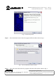
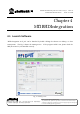
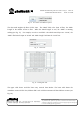
Fig. 16 Scan button and additional options.
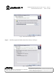
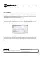
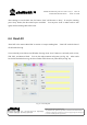
The data mask supplies the filter of EPC data. The “Mask” field is the bytes of filter; the “Mask
Length” is the number of bits to filter. When the “Mask Length” is zero, the “Mask” is meaning
nothing (see Fig. 17). For example, in order to read EPC code which started bytes are “A1A0”, the
“Mask” filed must be input as “A1A0” and “Mask Length” field must be “0x10” bits.
Fig. 17 Data mask.
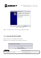
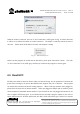
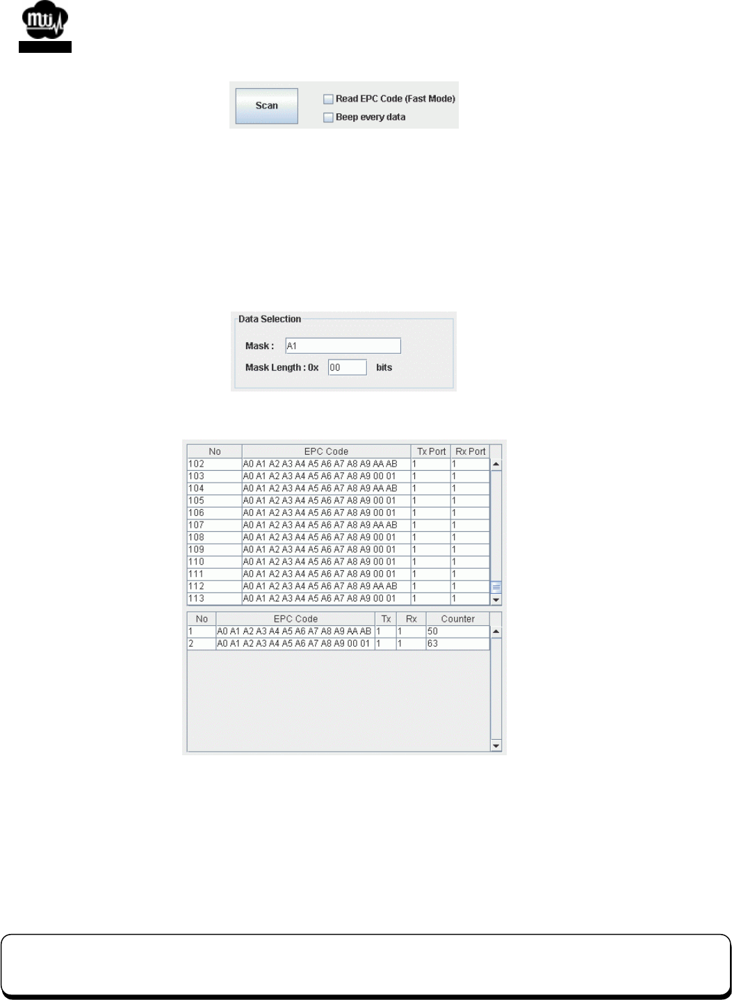
Fig. 18 Reading EPC data.
The upper table shows each EPC data entry received from Reader. The lower table shows the
cumulative counter of EPC data, different EPC code or different antenna will have different counter (see
Fig. 18).