
User Manual


RFID Reader DEMO Integration User Guide V1.05_02 PAGE: 6
43-RFID INTEGRATION UG105 DATE: 12/13/2006
台揚集團智慧財產
任何未經授權逕予複製、重製、公開或使用本文之行為,將被視為侵害
台揚集團之智慧財產權,將可因此負擔法律責任。
MTI Group Proprietary Information
Any unauthorized use, duplication, reproduction, or disclosure of this document may be
considered as infringement of MTI Group
’s intellectual property rights, the infringer may
be accused and liable applicable legal penalties.
台揚科技股份有限公司
MICROELECTRONICS TECHNOLOGY INC.
ISO 9001 Certified
Table of Figures
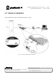
Fig. 1 Interface installation with related ports......................................................................9
Fig. 2 Start the setup wizard.............................................................................................11
Fig. 3 Select the destination location to install...................................................................11
Fig. 4 Select start menu folder to install.............................................................................12
Fig. 5 Ready to install.......................................................................................................12
Fig. 6 Finish the installation...............................................................................................13
Fig. 7 Confirmation of uninstallation.................................................................................13
Fig. 8 Uninstall MTI RFID Integration successfully...........................................................14
Fig. 9 Running screen........................................................................................................15
Fig. 10 Connection dialog - TCP Server............................................................................16
Fig. 11 Connection dialog - TCP Client.............................................................................17
Fig. 12 TCP Connection icon............................................................................................17
Fig. 13 Parameters of antenna and power..........................................................................18
Fig. 14 Status of antenna’s switch.....................................................................................18
Fig. 15 RF Power icon......................................................................................................18
Fig. 16 Scan button and additional options........................................................................19
Fig. 17 Data mask.............................................................................................................19
Fig. 18 Reading EPC data.................................................................................................19
Fig. 19 Read all panel........................................................................................................20
Fig. 20 Read data of banks................................................................................................21
Fig. 21 Antenna selection and power adjuster....................................................................21
Fig. 22 Memory bank selection.........................................................................................22
Fig. 23 Writing data..........................................................................................................22
Fig. 24 GPIO panel...........................................................................................................23