MTI RU-824 RFID Reader Quick Guide Version 1.1 MTI Group Proprietary Information Any unauthorized use, duplication, reproduction, or disclosure of this document may be considered as infringement of MTI Group’s intellectual property rights, the infringer may be accused and liable applicable legal penalties.
Chapter 1 1.1 1.2 Chapter 2 2.1 2.2 2.3 2.4 Introduction........................................................... 3 Purpose ................................................................ 3 Trademarks .......................................................... 3 Product Introduction ............................................. 4 Product Specification ........................................... 4 Product and Accessories ..................................... 5 Hardware Installation .......................
Chapter 1 Introduction 1.1 Purpose This guide will help you set-up and configure your RU-824 RFID reader. Following the installation instructions should be quick and easy. 1.2 Configuration This guide covers the following configuration Configuration Part number US band RFID Reader RU-824-100 EU band RFID Reader RU-824-110 1.3 Trademarks The product described in this guide is a licensed product of Microelectronics Technology Inc.
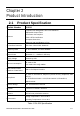
Chapter 2 Product Introduction 2.
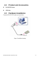
2.2 Product and Accessories RU-824 RFID Reader USB Cable 2.3 Hardware Installation Connected RU-824 RFID reader as shown below Figure 1 Installation drawing MICROELECTRONICS TECHNOLOGY INC. P.
2.4 2.4.1 Software (Tracer) Installation Tracer overview The Tracer application is a .NET-based graphical user interface (GUI) tool that uses the Indy RFID Host Library API to exercise the functionality of the reader platform. Tracer is dynamically linked to the Indy RFID Host Library. Therefore, there is no need to install the interface library separately. However, the USB host driver must be installed prior to using Tracer. Tracer is supported on Windows XP only.
2. When prompted, designate the desired installation directory. The default is [Program Files]\IMPINJ\Tracer v2.3.0\. 3. Installation includes the C++ runtime libraries and adds a desktop shortcut to the Tracer application. 1. To Start the Tracer application: Double click the desktop shortcut, or Use the Start Menu. For example, if installed to the default directory: Click Start, Select All Programs, IMPINJ, Impinj Tracer v2.3.0, Click Tracer. 2.4.
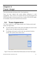
Chapter 3 Tracer Usage This section describes the features of the Tracer Application. Tracer has been adapted with reader platform differences in mind. Consequently, Tracer version 2.3.0 supports both the Indy R1000-based and R2000-based reader, but some functions are not used on RU-824 RFID reader. In this situation, they are not described in this document. 3.1 Tracer Appearance The Tracer consists of a main display window and a floating control panel window. See figure below.
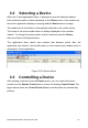
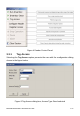
3.2 Selecting a Device When the Tracer application starts, it attempts to open all attached readers. Each attached reader is listed separately in the Device menu. If no readers are found, the application displays a warning and the Device menu is empty. The reader that is found first is automatically selected as the active device. The name of the active reader device is always displayed on the window caption. To change the active reader, make a selection from the Device menu as shown in the figure below.
Figure 4 Reader Control Panel 3.3.1 Tag Access Selecting the Tag Access option presents the user with the configuration dialog shown in the figure below. Figure 5 Tag Access dialog box, Access Type Read selected MICROELECTRONICS TECHNOLOGY INC. P.
From the Tag Access dialog box, the user can perform many different access operations against tags as follows. 3.3.1.1 Access Type Read Selecting the Read Access Type option displays the configuration dialog shown in the figure above.
Figure 6 Tag Access dialog box, Access Type Write selected From this dialog, the user can perform a write operation against tags and can provide the following configurable parameters: Memory Bank—the target for the write operation, has selectable values of either the EPC, TID, User, or Reserved memory bank Offset—the offset in hexadecimal of the first 16-bit word to write from the target memory bank Count—the number of 16-bit words to read, starting at Offset Value 1—the hexadecimal value of
3.3.1.3 Access Type Kill The kill operation allows the user to render any tag with a matching access and kill password as permanently non-functional. Selecting the Kill Access Type option displays the configuration dialog shown in the figure below. Figure 7 Tag Access dialog box, Access Type Kill selected Note: Tags with a value of zero for their password are not expected to respond to the kill command. 3.3.1.
Figure 8 Tag Access dialog box, Access Type Lock selected Note that all permissions are set in a single operation. In many circumstances, it may be desirable to leave one or more of the target passwords or permissions in an unmodified state. To do this, select the NO_CHANGE option for those targets. 3.4 Configure Reader The Tracer application allows the user to configure many of the settings of the attached readers. To access the configuration panel: Note: This is a quick guide for RU-824 RFID reader.
Figure 9 Accessing Reader Configuration The Tracer Reader Configuration dialog contains many function-specific pages, each of which is listed on the left-hand side selection bar. The current selection is always indicated by a visual highlight. For example, in the figure below, the Settings page is active. Figure 10 Reader Configuration Dialog Box MICROELECTRONICS TECHNOLOGY INC. P.
3.4.1 Settings Page When the Reader Configuration dialog first opens, it displays the Settings page shown in the figure above. The settings displayed are the current settings on the reader. From this page, you can view and/or configure the following items: Operating Region (Read only, set within the reader) Link Profile Data Format (Compact, Normal or Extended) Operational Mode (Continuous Mode or Discontinuous Mode) Inventory Algorithm (Fixed Q or Dyanmic Q) 3.4.
figure below, this page displays the active selection criteria of the current reader. The Display Criterion # spin box allows you to select the criteria currently being viewed. It has a range of one (1) up to the value displayed under Active Criteria. The Load button causes the application to perform a direct query to the current reader and reload the page with the retrieved select criteria settings. To change the select criteria parameters for the active reader, click the Edit button.
query settings, the parameters for the selected singulation algorithm, and whether select and post singulation filters should be utilized during inventory, read, write and similar operations. The figure below shows an example of the Inventory Algorithm View panel. The Load button queries the current reader and refreshes the values displayed on the Algorithm Settings page. To modify the algorithm settings for the current reader, click the Edit button.
3.4.5 Post Singulation Criteria Page Use the Post Singulation page to view and configure reader settings that define the manner in which tags and post singulation are filtered (based on all or part of the tag’s EPC). The Display Criterion # spin box allows you to select the criteria currently being viewed. It has a range of one (1) up to the value displayed under Active Criteria.
3.4.6 GPIO Pin Configuration Page RU-824 does not support GPIO configuration 3.4.7 OEM Data Page The OEM Data page allows the user to read product data from the OEM area on the Indy Firmware microcontroller. Figure 15 Inventory Algorithm Edit Page 3.4.8 RF Channel Definitions Page The RF (Radio Frequency) Channel Definitions page provides to view the reader’s frequency channels. An example of this page is shown below in the figure below. The table is limited by F/W configuration.
Figure 16 RF Channels Page MICROELECTRONICS TECHNOLOGY INC. P.
the detail channel definition of US and EU band are as follow. Channel Frequency Channel Frequency Channel 0 902.75 MHz Channel 25 915.25 MHz Channel 1 903.25 MHz Channel 26 915.75 MHz Channel 2 903.75 MHz Channel 27 916.25 MHz Channel 3 904.25 MHz Channel 28 916.75 MHz Channel 4 904.75 MHz Channel 29 917.25 MHz Channel 5 905.25 MHz Channel 30 917.75 MHz Channel 6 905.75 MHz Channel 31 918.25 MHz Channel 7 906.25 MHz Channel 32 918.75 MHz Channel 8 906.
version information for the Indy device, Indy Firmware, Indy USB host driver, and Indy Host Library API Interface. The figure below shows a sample About Page. Figure 17 About Reader Page 3.4.10 Troubleshooting Panel The Troubleshooting page provides access to the Indy Firmware error register as well as the ability to clear the error and reset the Indy Firmware. See the figure below. MICROELECTRONICS TECHNOLOGY INC. P.
Figure 18 Troubleshooting Page Note: Performing a Reset Firmware operation causes a reset of the connection to the current reader. The reader will no longer be accessible via the application until the application is restarted. MICROELECTRONICS TECHNOLOGY INC. P.
Appendix A: Federal Communication Commission Interference Statement This equipment has been tested and found to comply with the limits for a Class B digital device, pursuant to Part 15 of the FCC Rules. These limits are designed to provide reasonable protection against harmful interference in a residential installation.
Appendix B: Declaration of Conformity for R&TTE Directive 99/5/EC We, MICROELECTRONICS TECHNOLOGY INC.
issues relevant for this declaration. European Representative Manufacturer Contact Company: MICROELECTRONICS TECHNOLOGY INC. Address: No.1,Innovation Road II, Company: MICROELECTRONICS ECHNOLOGY INC. Hsinchu Address: No.1,Innovation Road II, Hsinchu Science Park,Hsinchu 300, Taiwan, R.O.C. Science Park,Hsinchu 300, Taiwan, R.O.C.