1) Open the box and checking Page 1 2) Safety instructions Page 1 3) Operating determinations Page 2 4) Description of the device Page 3 5) Installation Page 4 6) Control Board Operation Page 8 7) DMX512 Channel Function Page 9 8) Technical specifications Page 18 9) Beampath Page 19 10)Maintenance and cleaning Page 20 11) Structure of the fixture Page 21 12) Electrical diagram Page 22 13) Common faulty maintain Page 23 14) Component antitheses Page 24 15) Main PCB Page 26 16) D
1.Open the box and checking Congratulations on choosing our products! Please carefully read this instruction manual in its entirety and keep it well for using reference. This manual contained about the installation and the relative using information of this products. Please according to this manual's relative speaking when using this equipment. This equipment was made of new style, high intensity plastic . It fully shows the modem times light characteristic with beauty structure.
Ø by the plug. Never pull out the plug by tugging the power-cord. Ø This device falls under protection class I. Therefore it is essential to connect the yellow/green conductor to earth. Ø The electric connection, repairs and servicing must be carried out by a qualified employee. Ø Do not connect this device to a dimmer pack. Ø Do not switch the fixture on and off in short intervals as this would reduce the lamp' s life. Ø During the initial start-up some smoke or smell may arise.
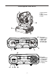
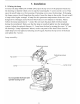
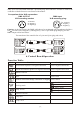
4.Description of the device 1 - Moving head 2 - Yoke 3- Carry handles 4 - Base Rear panel: 5 -Power switch 6 -DMX output 7- DMX input 8- Power cord 9- Fuse holder LAMP:MSD 250/2 MSD 250 SERIAL DATA LINK OUT DMX IN 1=GND 2=SIG.3=SIG.+ POWER SWITCH FUSE LIGHTING CONTROL PROTOCOL:DMX512 Serial number: POWER SUPPLY T 3.15A@230V T 6.
5.2 Lamp adjust The lamp holder is aligned at the factory. Due to differences between lamps , fine adjustment may improve light performance. Strike the lamp, open the shutter and the iris, set the dimmer intensity onto 100% and focus the light on a flat surface (wall).
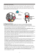
Colour/Static gobo-wheel: Gently bend out the gobo holder to release it from the fixative holes and eject it from the pressing snap. Press the ends of the fixation-ring together with an appropriate tool and remove it. Remove the gobo and insert the new gobo. Press the ends of the fixation-ring together and insert it in the front of the gobo. Put the gobo holder back under the pressing snap and push it to the 3 fixative notches. gobo pressing snap holder 5.
Ø The projector can be placed directly on the stage floor or rigged in any orientation on a truss without altering its operation characteristics. Ø For overhead use, always install a safety-rope that can hold at least 10 times the weight of the fixture. You must only use safety-ropes with screw-on carabines. Pull the safety-rope through the two apertures on the bottom of the base and over the trussing system etc. Insert the end in the carabine and tighten the fixation screw.
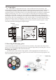
Only use a stereo shielded cable and 3-pin XLR-plugs and connectors in order to connect the controller with the fixture or one fixture with another. Occupation of the XLR-connection: DMX-input XLR mounting-plug: DMX-OUTPUT XLR mounting-socket: 1- Ground 2 - Signal (-) 3 - Signal (+) 1 1 - Ground 2 - Signal (-) 3 - Signal (+) Caution: At the last fixture, the DMX-cable has to be terminated with a terminator.
Control board operation way: LED MODE ENTER UP DOWN 1.Select working mode by pressing MODE. 2.Press ENTER to confirm the selection. 3.Press UP and DOWN to select working condition. 4.Press ENTER to confirm the selection. 7.
CHANNEL 1: PAN Effect Value 255 100 0 0 Clockwise 53 0 rotate CHANNEL 2: TILT 10 Value Effect 255 100 Anti-clockwise 280 rotate 0 0
CHANNEL 3: PAN FINE (proportional) • Value Effect 255 100 Fine control of tilt movement 0 0 CHANNEL 4: TILT FINE (proportional) 11 Value Effect 255 100 Fine control of tilt movement 0 0
CHANNEL 5: Speed of PAN/TILT movement Value Slow Fast Effect 255 100 0 0 Slow fast CHANNEL 6: Lamp on/off & reset • Value 12 Effect 240-255 95-100 No function 230-239 91-94 Lamp off after 3 seconds 140-229 55-90 No function 128-139 50-54 Lamp on after 3 seconds,Reset 0-127 0-49 No function
CHANNEL 7: Color1 Value Effect 128-255 50-100 Forwards rainbow effect from slow to fast 112-127 44-49 Pink 96-111 37-43 Blue 80-95 31-36 Orange 64-79 25-30 Green 48-63 19-24 Magenta 32-47 12-18 Yellow 16-31 6-11 Red 0-15 0-5 Open/white Value Effect 222-255 87-100 Light Blue 185-221 72-86 Pale purple 148-184 57-71 Light Orange 111-147 43-56 Static gobo 3 74-110 28-42 Static gobo 2 37-73 14-27 Static gobo 1 0-36 0-13 White CHANNEL 8: Static gobo /color2 13
CHANNEL 9: Prism Value Effect 128-255 100 3-facet prism 0-127 0 No function 133-255 53-100 Backwards rotation from slow to fast 128-132 51-52 No rotation 5-127 3-50 Forwards rotation from fast to slow 0-4 0-2 No rotation CHANNEL 10: 3-facet prism rotation Value 14 Effect
CHANNEL 11: Rotating gobos Effect Value 224-255 88-100 Rotate gobo wheel continue rotation from slow to fast 160-223 63-87 Rotate gobo 5 128-159 50-62 Rotate gobo 4 96-127 37-49 Rotate gobo 3 64-95 25-36 Rotate gobo 2 32-63 12-24 Rotate gobo 1 0-31 0-11 Open/hole CHANNEL 12:Rotating gobo index, rotating gobo rotation 15 Value Effect 159-255 62-100 Backwards gobo rotation from slow to fast 61-158 24-61 Forwards gobo rotation from slow to fast 0-60 0-23 Gobo indexing (0-540 )
CHANNEL 13: Zoom,frost,UV filter Effect Value UV-filter 224-239 87-92 Frost 208-223 82-86 Zoom 26 192-207 75-81 Zoom 24 176-191 68-74 Zoom21 160-175 62-67 Zoom 18 128-159 50-61 Zoom 15 112-127 43-49 UV-filter 96-111 37-42 Frost 80-95 31-36 Zoom 26 64-79 24-30 Zoom 24 48-63 18-23 Zoom21 32-47 12-17 Zoom 18 0-31 0-11 Zoom 15 Zoom without focus corection 93-100 Zoom without focus corection 240-255 CHANNEL 14: Focus(proportional) Near Far 16 Value Effect 255 1
CHANNEL 15:Shutter, strobe Value Effect 224-255 87-100 Shutter Open 192-223 75-86 Random strobeeffect from slow to fast 160-191 62-74 Shutter Open 128-159 50-61 Pulse-effect in sequences from slow to fast 96-127 37-49 Shutter Open 64-95 25-36 Strobe-effect from slow to fast (max 10flashes/s) 32-63 12-24 Shutter Open 0-31 0-11 Shutter closed CHANNEL 16: Dimmer intensity(proportional) Brightest Value Effect 255 100 Brightest 0 0 Black Black 17
8. Technical specifications US-model: Voltage............................AC100/110/120V , 50/60Hz Fuse................................ T 6.3 A@120V EU-model:Voltage............................AC220/230/240V ,50/60Hz Fuse ................................T3.
9.
10. Maintenance and cleaning It is absolutely essential that the fixture is kept clean and that dust, dirt and smoke-fluid residues must not buildup on or within the fixture. Otherwise, the fixtures light-output will be significantly reduced. Regular cleaning willnot only ensure the maximum light-output, but will also allow the fixture to function reliably throughout its life.
11.
12.
COMMEN FAULTY MAINTAIN 13. Commen faulty maintain FAULTY PHONMENON FAULTY ANALYSIS FAULTY PART PART No.
ROTATION GOBO WHEEL CAN NOT CHANGE GOBO MOTOR FOR GOBO WHEEL FAULTY 42BYGH026-1MOTOR 15-00-0033-00 MOTOR OF DAMP POLE DAMP POLE 34-01-RD2105_03-00 16HY0002MOTOR 15-00-0007-00 ROTATION GOBO WHEEL 34-01-RD2107_38-00 42BYGH026-1MOTOR 15-00-0033-00 MOTOR FOR ZOOM FAULTY 42BYGH004-02MOTOR 15-00-0073-01 MOTOR FOR FIXED GOBO WHEEL FAULTY 42BYGH004-02MOTOR 15-00-0073-01 DAMPER FAULTY DAMP POLE 34-01-RD2105_03-00 PRISM WHEEL FAULTY 42BYGH0026-2MOTOR 15-00-0079-00 DAMPER FAULTY DAMP POLE 34
IC13 TO IC16 ON 2107L PCB 00-7528-01 D/A CONVERSION CHIP IC17 TO IC20 ON 2107L PCB DRIVER CHIP 00-6219-01 CPU ON 2107L PCB 00-89S52-00 SOFTWARE CHIP IC21 TO IC23 ON 2107S PCB SOFTWARE CHIP 00-77E58-00 IC24 TO IC26 ON 2107S PCB DRIVER CHIP 00-6219-01 CPU ON 2107S PCB 00-89S52-00 SOFTWARE CHIP CPU ON DISPLAY PCB 00-89S8252-00 SOFTWARE CHIP TILT HORGE PCB 2105HRT.PCB 26-2A-YX2105HRT-00 TILT SENSOR PCB 26-2A-YX2105GM-00 2105GM.PCB 26-2A-YX2105GM-00 PAN SENSOR PCB 2105GM.PCB PAN HORGE PCB 2105HRP.
VMM2 VMM1 3772 VCC GND GND GND GND 13 12 15 14 P33 P32 A1 P34 C28 C27 X1 X2 24MHZ Y1 A0 17 16 20 R43 10K 31 1 2 3 4 5 6 7 8 P10 P11 P12 P13 P14 P15 P16 P17 19 18 9 E1 VCC 7 16 22 18 17 6 5 Vbb1 Vbb2 X1 X2 10U/50V VCC VCC +30 14 R1 R2 0.5 0.5 9 FR104 FR104 D2 D1 1 2 3 4 11 8 15 12 Mb2 Ma2 Ma1 Mb1 RC C1 E1 C2 E2 1 R26 15K C39 104 VCC P00 P01 P02 P03 P04 P05 P06 P07 R29 470 R27 15K VCC C3 223 C4 223 C13 104 R30 470 VCC 0.5 R11 1K +30 0.
E2 17 16 9 10U/50V R9 10K 19 18 31 15 14 13 12 1 2 3 4 5 6 7 8 P26 P25 X1 X2 VCC P17 RELY CMP P12 P13 P14 ENTER UP K4 DOWN K3 P24 89S8252 RD WR RESET X1 X2 EA/VP T1 T0 INT1 INT0 P10 P11 P12 P13 P14 P15 P16 P17 U1 C1 C2 X2 24MHZ X1 Y1 RXD TXD ALE/P PSEN P20 P21 P22 P23 P24 P25 P26 P27 P00 P01 P02 P03 P04 P05 P06 P07 VCC C3 104 10 11 30 29 21 22 23 24 25 26 27 28 39 38 37 36 35 34 33 32 P22 P23 P24 P25 P26 P27 100 100 R10 R11 P00 P01 P02 P03 P04 P05 P06 P07 C5 104
5 P20 C1 221 R33 20K 1 2 3 4 5 6 7 8 9 10 11 12 GND X1 X2 P32 P33 P11 P12 P13 P14 P15 R47 10K P36 VCC E1 10U/50V 1R8 R1 1K8 R17 18 4 VrefB VrefA 17 16 20 9 19 18 15 14 31 13 12 1 2 3 4 5 6 7 8 C17 102 L6219 OUT1A OUT2A SENSE2 COMP2 OUT 2B GND GND I02 I12 PHASE2 VREF2 RC2 U1 19 RfbB 1 AN-GND DACA/B WR CS P11 6 P15 16 GND 15 C18 102 VS SENSE1 COMP1 OUT1B I01 GND GND I11 PHASE1 VREF1 RC1 VSS 4 3 2 1 20 OUT-B P37/RD P36/WR GND RESET X1 X2 P35/T1 P34/T0 EA/VP P33/INT1 P3
5 R47 10K P20 C1 221 VCC E1 10U/50V 1R8 R1 1K8 R17 R33 20K 1 2 3 4 5 6 7 8 9 10 11 12 18 4 GND VrefB VrefA P32 P33 X1 X2 13 12 P12 P13 P14 P15 17 16 20 9 19 18 15 14 31 1 2 3 4 5 6 7 8 C17 102 L6219 OUT1A OUT2A SENSE2 COMP2 OUT 2B GND GND I02 I12 PHASE2 VREF2 RC2 U1 P12 6 P15 16 GND 15 19 RfbB 1 AN-GND DACA/B WR CS C18 102 VS SENSE1 COMP1 OUT1B I01 GND GND I11 PHASE1 VREF1 RC1 VSS 4 3 2 1 20 OUT-B P37/RD P36/WR GND RESET X1 X2 P35/T1 P34/T0 EA/VP P33/INT1 P32/INT0