Operating Manual MHX920 900 MHz Spread Spectrum OEM Transceiver Revision 0.10, January 9, 2006 Microhard Systems Inc. #17, 2135 – 32nd Ave N.E. Calgary, Alberta T3K 4Z4 Phone: (403) 248-0028 Fax: (403) 248-2762 www.microhardcorp.
Warranty Microhard Systems Inc. warrants that each product will be free of defects in material and workmanship for a period of one (1) year for its products. The warranty commences on the date the product is shipped by Microhard Systems Inc. Microhard Systems Inc.’s sole liability and responsibility under this warranty is to repair or replace any product which is returned to it by the Buyer and which Microhard Systems Inc. determines does not conform to the warranty.
MHX920 Regulatory Requirements PLEASE READ THIS SECTION CAREFULLY WARNING: To satisfy FCC RF exposure requirements for mobile transmitting devices, a separation distance of 23 cm or more should be maintained between the antenna of this device and persons during device operation. To ensure compliance, operations at closer than this distance is not recommended. The antenna used for this transmitter must not be co-located in conjunction with any other antenna or transmitter.
Contents Warranty ....................................................................................................................................................................... ii Warranty Diclaims........................................................................................................................................................ ii Indemnification.......................................................................................................................................
2. General 2.0 Product Overview The MHX920 is a high-performance embedded wireless data transceiver. Operating in the 902 - 928 MHz ISM band, this frequency-hopping spreadspectrum module is capable of providing reliable wireless data transfer between almost any type of equipment which uses an asynchronous serial interface. The small-size and superior RF performance of this module make it ideal for many applications.
TDMA (time division multiple access) support, allowing multi-slave access in point-to-point mode. roaming ability, allowing repeaters and slaves to resynchronize with a new master if the synchronization pulse from the original master is lost. While the typical application for the MHX920 is to provide a short- to midrange wireless communications link between DTEs, it can be adapted to almost any situation where an asynchronous serial interface is used and data intercommunication is required. 2.
MHX-920 Operating Manual: Chapter2 General 3
3. Installation 3.0 Overview Qualified and experienced personnel must carry out the installation, removal or maintenance of all antenna components. The MHX920 complies with FCC part 15 at the modular level for operation in the license-free 902-928 MHz ISM band. This chapter provides guidelines for installing and deploying equipment which incorporates the MHX920 module. 3.
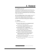
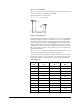
Figure 1 Gain Calculation The power level has been set to 30dBm (1W) on the transmitter, and the receiver sensitivity for the MHX920 is -108dBm. System gain would be calculated to be: 30 - 2 + 6 + 3 - 2 + 108 = 143 dB.
Once the equipment is deployed, you can verify the signal strength by entering into Command Mode and reading Register S123. This register provides the average signal strength in dBm. The minimum strength for communication is roughly -108dBm. For consistent reliable communication, you should try to deploy the equipment such that signal strength exceeds -95dBm. 3.
3.2.2 WARNING: To satisfy FCC RF exposure requirements for mobile transmitting devices, a separation distance of 23 cm or more should be maintained between the antenna of this device and persons during device operation. To ensure compliance, operations at closer than this distance is not recommended. The antenna used for this transmitter must not be co-located in conjunction with any other antenna or transmitter.
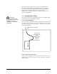
When installing the cable, always begin fastening at the top near the antenna connector/surge arrestor. The cable must be supported at the top with a hose clamp or wrap lock, and at 5 ft intervals down the length of the tower. Over-tightening the fasteners will dent the cable and reduce performance. If properly grounded surge arrestors are not installed at both the top and the bottom of the cable, then the cable should be grounded to the tower at these locations using a cable grounding kit.
Examples: FCC and Industry Canada Regulations allow up to 36dBm effective radiated power (ERP). Therefore, the sum of the transmitted power (in dBm), the cabling loss and the antenna gain cannot exceed 36dBm with respect to the isotropic radiator.
A. Approved Antennas Group Part Number Description Quarter Wave MHS031010 <1.5dBi, 900MHz 1/4 Wave Antenna Reverse SMA Right Angle MHS031020 <1.5dBi, 900MHz 1/4 Wave Antenna Reverse SMA Straight MHS031030 <1.5dBi, 900MHz 1/4 Wave Antenna Reverse SMA Right Angle MHS MHS031040 <1.5dBi, 900MHz 1/4 Wave Antenna Reverse SMA Straight MHS MHS031050 <1.5dBi, 900MHz 1/4 Wave Antenna MCX Right Angle MHS MHS031060 <1.
MHX-920 Operating Manual:Glossary 11