
User's Manual


MHX-920 Operating Manual:Glossary 5
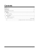
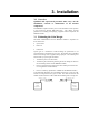
Figure 1 Gain Calculation
The power level has been set to 30dBm (1W) on the transmitter, and the
receiver sensitivity for the MHX920 is -108dBm.
System gain would be calculated to be:
30 - 2 + 6 + 3 - 2 + 108 = 143 dB.
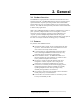
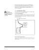
Figure 2 System Deploying
When deploying your system, care must be taken to ensure the path loss
(reduction of signal strength from transmitter to receiver in dB) between
equipment does not exceed the system gain (140 dB in the above example).
It is recommended to design for a gain margin of at least 20 dB to ensure
reliable communication. Gain margin is the difference between system gain
and path loss. Referring to the same example, suppose the path loss is 100
dB, the gain margin would be 40 dB, which is more than adequate for
reliable communication.
Path loss is a very complicated calculation which mainly depends on the
terrain profile, and the height of the antennas off the ground.
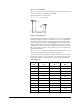
The following table provides path loss numbers for varying antenna heights
and antenna separation: These numbers are real averages taken from rural
environments. They do not apply to urban, non-line-of-sight environments.
Table 2 Path Loss
Distance
(km)
Base Height
(m)
Mobile Height
(m)
Path Loss
(dB)
5 15 2.5 116.5
5 30 2.5 110.9
8 15 2.5 124.1
8 15 5 117.7
8 15 10 105
16 15 2.5 135.3
16 15 5 128.9
16 15 10 116.2
16 30 10 109.6
16 30 5 122.4
16 30 2.5 128.8
Base Height (m)
Mobile
Heigh
t
(m)
Distance (km)