
User's Manual


Chapter3 Installation 3
3. Installation
3.0 Overview
The N920BF complies with FCC part 15 at the modular level for operation
in the license-free 902-928 MHz ISM band. This chapter provides
guidelines for installing and deploying equipment which incorporates the
N920BF module.
3.1 Estimating the Gain Margin
Successful communication between N920BF modules is dependent on three
main factors:
System Gain
Path Loss
Interference
System gain is a calculation in dB describing the performance to be
expected between a transmitter-receiver pair. The number can be calculated
based on knowledge of the equipment being deployed. The following four
factors make up a system gain calculation:
1. Transmitter power (user selectable)
2. Transmitter gain (transmitting antenna gain minus cabling loss between
the transmitting antenna and the N920BF module)
3. Receiver gain (Receiving antenna gain minus cabling loss between the
receiving antenna and the module)
4. Receiver sensitivity (Specified as -108dBm on the N920BF module)
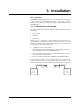
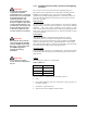
In the following illustration, the transmitting antenna has a gain of 6 dB,
and the receiving antenna has a gain of 3 dB. The cable loss between the
module and the antenna is 2 dB on both the transmitting and receiving side.
Transmitter
30 dBm
Output Power
Receiver
Sensitivity =
-105 dBm
Cable Loss = 2 dBCable Loss = 2 dB
Antenna Gain = 6 dB
Antenna Gain = 3 dB