Operating Manual p400 Pico 900MHz 1W FHSS / 400MHz 2W License Band Module Revision 0.20, September 16, 2014 Microhard Systems Inc. www.microhardcorp.
Warranty Microhard Systems Inc. warrants that each product will be free of defects in material and workmanship for a period of one (1) year for its products. The warranty commences on the date the product is shipped by Microhard Systems Inc. Microhard Systems Inc.’s sole liability and responsibility under this warranty is to repair or replace any product which is returned to it by the Buyer and which Microhard Systems Inc. determines does not conform to the warranty.
p400 Regulatory Requirements NOTE: This equipment has been tested and found to comply with the limits for a Class B digital device, pursuant to part 15 of the FCC Rules. These limits are designed to provide reasonable protection against harmful interference in a residential installation. This equipment generates, uses and can radiate radio frequency energy and, if not installed and used in accordance with the instructions, may cause harmful interference to radio communications.
WARNING: ANTENNA: FCC: Changes or modifications not expressly approved by Microhard Systems Inc. could void the user’s authority to operate the equipment. This device has been tested with UFL and Reverse Polarity SMA connectors with the antennas listed in Appendix A When integrated in OEM products, fixed antennas require installation preventing endusers from replacing them with non-approved antennas. Antennas not listed in the tables must be tested to comply with FCC Section 15.
p400 Regulatory Requirements Remarque : Cet équipement a été testé et déclaré conforme aux limites d'un appareil numérique de classe B, conformément à la partie 15 des règles FCC. Ces limites sont conçues pour fournir une protection raisonnable contre les interférences nuisibles dans une installation résidentielle.
WARNING: ANTENNE: FCC: Les changements ou modifications non expressément approuvés par Microhard Systems Inc. pourrait annuler le droit de l'utilisateur à utiliser l'équipement. Ce dispositif a été testé avec UFL et SMA à polarité inverse connecteurs avec les antennes énumérées à l'annexe A Lorsqu'il est intégré dans les produits OEM, antennes fixes nécessitent une installation empêchant les utilisateurs finaux de les remplacer par des antennes non approuvées.
Contents Warranty ....................................................................................................................................................................... ii Warranty Diclaims ........................................................................................................................................................ ii Indemnification......................................................................................................................................
2. General 2.0 Product Overview The p400 is a high-performance embedded wireless data transceiver. Operating in the 902 - 928 MHz ISM band, this frequency-hopping spreadspectrum module is capable of providing reliable wireless data transfer between almost any type of equipment which uses an asynchronous serial interface. The small-size and superior RF performance of this module make it ideal for many applications.
TDMA (time division multiple access) support, allowing multi-slave access in point-to-point mode. roaming ability, allowing repeaters and slaves to resynchronize with a new master if the synchronization pulse from the original master is lost. While the typical application for the p400 is to provide a short- to midrange wireless communications link between DTEs, it can be adapted to almost any situation where an asynchronous serial interface is used and data intercommunication is required. 2.
3. Installation 3.0 Overview The p400 complies with FCC part 15 at the modular level for operation in the license-free 902-928 MHz ISM band. This chapter provides guidelines for installing and deploying equipment which incorporates the p400 module. 3.
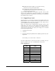
Figure 1 Gain Calculation The power level has been set to 30dBm (1W) on the transmitter, and the receiver sensitivity for the p400 is -108dBm. System gain would be calculated to be: 30 - 2 + 6 + 3 - 2 + 108 = 143 dB. Base Height (m) Mobile Height (m) Distance (km) Figure 2 System Deploying When deploying your system, care must be taken to ensure the path loss (reduction of signal strength from transmitter to receiver in dB) between equipment does not exceed the system gain (140 dB in the above example).
Once the equipment is deployed, you can verify the signal strength by entering into Command Mode and reading Register S123. This register provides the average signal strength in dBm. The minimum strength for communication is roughly -108dBm. For consistent reliable communication, you should try to deploy the equipment such that signal strength exceeds -95dBm. 3.2 Antennas and Cabling This section describes the recommended procedure for installing cabling and antennas for use with the p400 module. 3.2.
3.2.2 WARNING: To satisfy FCC RF exposure requirements for mobile transmitting devices, a separation distance of 23 cm or more should be maintained between the antenna of this device and persons during device operation. To ensure compliance, operations at closer than this distance is not recommended. The antenna used for this transmitter must not be co-located in conjunction with any other antenna or transmitter.
WARNING: MAXIMUM EIRP FCC and IC Regulations allow up to 36dBm effective isotropically radiated power (EIRP). Therefore, the sum of the transmitted power (in dBm), the cabling loss and the antenna gain cannot exceed 36 dBm with respect to the isotropic radiator. WARNING: The p400 can only be used with any antennas listed in Appendix A. WARNING: Be careful with dBi vs dBd gains on antenna specifications. Antenna manufactures may not clearly indicate the gain on the antenna if it is dBd or dBi.
Examples: FCC and Industry Canada Regulations allow up to 36dBm effective isotropically radiated power (EIRP). Therefore, the sum of the transmitted power (in dBm), the cabling loss and the antenna gain cannot exceed 36dBm with respect to the isotropic radiator.
A.
B. Antenna / Separations This relates to operation in 400MHz Licensed Band Impedance (ohms) 50 50 Antenna Minimum Gain Maximum Gain Antenna Gain (dBi) 0 10 Minimum Separation Distance (cm) 24 77 RF EXPOSURE DISTANCE LIMITS r P G 4 S EIRP 4 S Sample calculation: S = 406.1/1500 mW/cm2 EIRP = 51 dBm = 1055/10 mW = 125893 mW (Worst Case) (Minimum Safe Distance, r) = EIRP 2000 76.7cm 4 S 4 (406.