Operating Manual HP900 OEM 900 MHz Spread Spectrum Wireless Module Revision 0.4, February 27, 2019 www.microhardcorp.
Warranty Microhard Systems Inc. warrants that each product will be free of defects in material and workmanship for a period of one (1) year for its products. The warranty commences on the date the product is shipped by Microhard Systems Inc. Microhard Systems Inc.’s sole liability and responsibility under this warranty is to repair or replace any product which is returned to it by the Buyer and which Microhard Systems Inc. determines does not conform to the warranty.
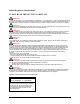
HP900 Regulatory Requirements PLEASE READ THIS SECTION CAREFULLY WARNING: To satisfy FCC RF exposure requirements for mobile transmitting devices, a separation distance of 35 cm or more should be maintained between the antenna of this device and persons during device operation. To ensure compliance, operations at closer than this distance is not recommended. The antenna used for this transmitter must not be co-located in conjunction with any other antenna or transmitter.
Co-Location with Cellular Modems FCC: The maximum calculated MPE ratio for the EUT with 3 dBi dipole antenna is 0.216 (evaluated at 35 cm), this configuration can be co-located with other antennas provided the sum of the MPE ratios for all the other simultaneous transmitting antennas incorporated in a host device is < 1.0 - 0.216 < 0.784. The following co-location were evaluated for mobile configurations: Industry Canada: The maximum calculated MPE ratio for the EUT with 3 dBi dipole antenna is 0.
Contents Indemnification ......................................................................................................................................................................... ii Proprietary Rights ................................................................................................................................................. ii HP900 Regulatory Requirements ...................................................................................................................
2. General 2.0 Product Overview The HP900 is a high-performance embedded wireless data transceiver. Operating in the 902 - 928 MHz ISM band, this frequency-hopping spreadspectrum module is capable of providing reliable wireless data transfer between almost any type of equipment which uses an asynchronous serial interface. The small-size and superior RF performance of this module make it ideal for many applications.
◼ TDMA (time division multiple access) support, allowing multi-slave access in point-to-point mode. ◼ roaming ability, allowing repeaters and slaves to resynchronize with a new master if the synchronization pulse from the original master is lost. While the typical application for the HP900 is to provide a short- to midrange wireless communications link between DTEs, it can be adapted to almost any situation where an asynchronous serial interface is used and data intercommunication is required. 2.
3. Installation 3.0 Overview The HP900 complies with FCC part 15 at the modular level for operation in the license-free 902-928 MHz ISM band. This chapter provides guidelines for installing and deploying equipment which incorporates the HP900 module. 3.
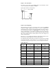
Figure 1 Gain Calculation The power level has been set to 30dBm (1W) on the transmitter, and the receiver sensitivity for the HP900 is -108dBm. System gain would be calculated to be: 30 - 2 + 6 + 3 - 2 + 108 = 143 dB. Base Height (m) Mobile Height (m) Distance (km) Figure 2 System Deploying When deploying your system, care must be taken to ensure the path loss (reduction of signal strength from transmitter to receiver in dB) between equipment does not exceed the system gain (140 dB in the above example).
Once the equipment is deployed, you can verify the signal strength by entering into Command Mode and reading Register S123. This register provides the average signal strength in dBm. The minimum strength for communication is roughly -108dBm. For consistent reliable communication, you should try to deploy the equipment such that signal strength exceeds -95dBm. 3.
Example of 50 Ω coplanar waveguide transmission line for 4-layer PCB Example of 50 Ω coplanar waveguide transmission line for 2-layer PCB To achieve a 50Ω characteristic impedance, the width of the transmission line must be chosen depending on: • the thickness of the transmission line itself (e.g. 35 μm) • the thickness of the dielectric material between the top layer and the next inner layer implementing the ground plane (e.g.
• The transmission lines width and spacing to GND must be uniform and routed as smoothly as possible: avoid abrupt changes of width and spacing to GND • Add GND stitching vias around transmission lines • Ensure solid metal connection of the adjacent metal layer on the PCB stack-up to main ground layer, providing enough vias on the adjacent metal layer • Route RF transmission lines far from any noise source and from any sensitive circuits • Avoid stubs on the transmission lines • Avoid signal rout
3.2.3 Internal Cabling The most common method for installing the module is to run a cable from the RPSMA antenna connector on the application PCB to a reverse TNC bulkhead connector on the chassis of the equipment as shown in Figure 3. This cable can be purchased from Microhard Systems.
3.2.4 WARNING: To satisfy FCC RF exposure requirements for mobile transmitting devices, a separation distance of 35 cm or more should be maintained between the antenna of this device and persons during device operation. To ensure compliance, operations at closer than this distance is not recommended. The antenna used for this transmitter must not be co-located in conjunction with any other antenna or transmitter.
WARNING: MAXIMUM EIRP FCC and IC Regulations allow up to 36dBm effective isotropically radiated power (EIRP). Therefore, the sum of the transmitted power (in dBm), the cabling loss and the antenna gain cannot exceed 36 dBm with respect to the isotropic radiator. WARNING: The HP900 can only be used with any antennas listed in Appendix A. WARNING: Be careful with dBi vs dBd gains on antenna specifications. Antenna manufactures may not clearly indicate the gain on the antenna if it is dBd or dBi.
Examples: FCC and Industry Canada Regulations allow up to 36dBm effective isotropically radiated power (EIRP). Therefore, the sum of the transmitted power (in dBm), the cabling loss and the antenna gain cannot exceed 36dBm with respect to the isotropic radiator.
A. Approved Antennas This radio transmitter [IC: 3143A-HP900] has been approved by Innovation, Science and Economic Development Canada to operate with the antenna types listed below, with the maximum permissible gain indicated. Antenna types not included in this list that have a gain greater than the maximum gain indicated for any type listed are strictly prohibited for use with this device.