#86892 8” x 12” Wood Turner’s Lathe Please read and understand all instructions before using this tool. Note: These instructions will show you how to assemble this machine, work its controls and maintain it for long life. It is not intended as an educational course on how to make parts using a lathe. Made in China for 340 Snyder Avenue Berkeley Heights, NJ 07922 For technical assistance, email Tech@micromark.
INTRODUCTION Your 8” x 12” Variable Speed Wood Lathe is a dependable tool designed to assist you in turning many types of projects. It is easy to assemble and to operate and is an ideal lathe for those just getting started in wood turning and experienced users alike. IMPORTANT: This manual is not intended as a “Teaching Guide” on how to perform wood turning. It describes functions of the components and gives general information about the lathe.
GENERAL SAFETY INFORMATION When turning a workpiece, always rough the wood to round form at a slow speed. If the lathe runs so fast that it vibrates, there is a risk that the workpiece could be thrown from the lathe causing injury. WARNING: To avoid mistakes that could cause serious injury, do not plug the lathe in until the following steps have been read and understood. Safety is a combination of common sense staying alert and knowing how to use your mini wood lathe.
1 Faceplate 2 Spindle 3 Headstock 4 Power cord 6 Speed control knob 7 Circuit breaker reset button 8 Switch 9 Tool rest banjo 10 Base lock lever 11 Tool rest lock lever (long) 12 Tool rest 6 13 Tailstock 14 Tailstock spindle 15 Hand wheel 16 Tailstock spindle lock lever (short) 17 Tailstock cup center 18 Tailstock lock lever 19 Flat wrench 20 Headstock spur center 21 Knock-out rod Note: 2-1/4” Faceplate and 2 hex keys are provided, but not shown.
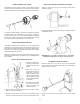
SPRING-LOADED LOCK LEVERS INSTALLING THE DRIVE SPUR AND LIVE CENTER Assemble the Spring-Loaded lock levers for the tailstock spindle and the tool rest. The shoulder screw (1) passes through the spring (2) and the handle lever (3) then finally into position on the machine. 1. Insert the shaft of the spur (1) into the hollow center of the headstock spindle. 2. Insert the shaft of the tailstock center (2) into the hollow center of the tailstock spindle.
ADJUSTMENTS SPEED CONTROL The variable speed control contains the electrical connections to the motor and has three external controls: ON/OFF switch, speed control knob, and the circuit breaker reset button. The speed control knob (3) sets the speed of the lathe to suit the weight of the workpiece or the type of tool being used. After the lathe has started turning, rotate the knob clockwise to increase the spindle speed. 1.
TAILSTOCK OPERATION TOOL REST OPERATION 1. Move the tailstock (5) by loosening the lock lever (1) and pushing the tailstock to the desired position on the bed. Lock by tightening the lock lever (1). 1. Loosen the lock lever (4) to move the tool rest (1) banjo to the right or left and back or wherever required. Then, tighten the lever (4) when the tool rest base is in the desired position on the lathe bed. 2. The spindle extends up to 2-1/2” from the tailstock housing.
Part No. Description Part No. Description Part No.
MAINTENANCE WARNING! For your own safety turn the switch OFF and remove the plug from the electrical outlet before performing maintenance or lubrication work on the lathe. 1. Blow out dust accumulation inside the motor the housing and the bed assembly frequently. If the tailstock has been used as a guide for drilling through the center of a workpiece also blow sawdust or shavings out of the center of both spindles. 2.