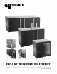
PRO-LINE REFRIGERATION E-SERIES ™ ™ USER MANUAL // www.micromatic.
CONTENTS 2 1 RECEIVING AND INSPECTING 3 2 3 3.1 3.2 3.3 3.4 3.5 3.6 3.7 3.8 4 4.1 4.2 4.3 4.4 5 5.1 5.2 5.
1 // RECEIVING AND INSPECTING Upon receiving your new Micro Matic Pro-Line™ Refrigeration E-Series™ equipment, check the package and the unit for any damages that may have occurred during transportation. Visually inspect the exterior of the package. If damaged, open and inspect the contents with the carrier. Any damage should be noted and reported on the delivering carrier’s receipt.
2 // SPECIFICATIONS Model Doors Tower Faucets Kegs HP AMP Crated Weight Length Width Height BTU (lbs) Refrigerant Charge (R-134 a) MDD23-E 1 1 1 1 1/6 2.5 172 24.5" 30.5" 40" 850 5.64 oz MBB/DD36-E 1 1 1 1 1/6 3.6 172 36.75" 29.5" 40" 850 6.35 oz MBB/DD58-E 2 2 3 3 1/3 6.5 318 59.5" 29.5 37" 2400 9.8 oz MBB/DD68-E 2 2 3 3 1/3 6.5 359 69.5" 29.5" 37" 2400 9.8 oz MBB/DD78-E 3 2 4 4 1/3 6.5 377 80" 29.5" 37" 2400 9.
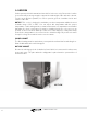
3 // INSTALLATION 3.1 UNCRATING Cut and remove the outer packaging. Cut the (4) four clamps that hold the refrigerator to the skid lift the unit off the skid. If machine was laid down during this operation leave the cabinet up right for 24 hours before plugging into power source. To install draft arm, first place rubber washer over draft arm mounting holes in cabinet top and put beer line connector down through hole. Next secure draft arm with four bolts provided.
3.4 LOCATION Units represented in this manual are intended for indoor use only. Be sure the location chosen has a floor strong enough to support the total weight of the unit and contents. For the most efficient operation, be sure to provide good air circulation inside and outside of the unit. NOTICE: This cooler is designed to maintain your beer temperature within the most desirable range of 32° to 38°F.
3.5 TAPPING INSTRUCTIONS The largest keg this cooler accepts is a half keg. The Sankey type is the most modern and easiest of all to tap with the available taps. The type of keg and tap you use will depend on the brand of beer your purchase. Your beer distributor can provide additional instructions and tips on how to maintain the beer to your satisfaction. Following these tapping instructions, place the keg in front of cabinet for tapping.
3.6 DATA PLATE The data plate in located inside the unit, near the top front left corner. Under no circumstances should the data plate be removed from the unit. The data plate is essential to identify the particular features of your unit and is of great benefit to installers, operators and maintenance personnel. It is recommended that, in the event the data plate is removed, you copy down the essential information in this manual for reference before installation. 3.
3.8 SHELVING INSTALLATION 1. Hook shelf rails onto shelf pilasters 2. Position all two shelf rails equal in distance from the floor for level shelves. 3. Wire shelves are oriented so that cross support bars are facing down. 4. Place shelves on shelf clips making sure all corners are seated properly. 4 // OPERATIONS 4.
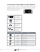
4.2 DESCRIPTION OF BUTTONS ON MODELS WITH DIGITAL CONTROLLER The Pro-Line™ dispenser is designed to maintain keg temperature within the most desirable range of 36° to 38°F. You can expect the Pro-Line™ unit to maintain temperature with the proper temperature control setting and in a normal environment. If a different setting is desired, follow these instructions to adjust the thermostat.
4.3 ELECTRONIC (DIGITAL) TEMPERATURE CONTROL HOW TO SEE THE SET POINT 1. Push and immediately release the key, the set point will be displayed. 2. Push and immediately release the to normal display. key or wait about five (5) seconds to return HOW TO CHANGE THE SET POINT 1. To change the set point number, push the key for more than two (2) seconds. 2. The number of the set point will be displayed and the “ ” or “ ” LED will blink. 3.
5 // MAINTENANCE 5.1 STAINLESS STEEL CARE AND CLEANING Proper cleaning of stainless steel requires soft cloths; never use steel pads, wire brushes or scrapers! Cleaning solutions need to be alkaline or non-chloride cleaners. Any cleaner containing chlorides will damage the protective film of the stainless steel. Chlorides are also commonly found in hard water, salts, household and industrial cleaners. If cleaner containing chlorides is used be sure to rinse repeatedly and dry thoroughly upon completion.
If you keep the condenser clean you will minimize your service expense and lower your electrical costs. Failure to maintain a clean condenser coil can initially cause high temperatures and excessive run times. Continuous operation with dirty or clogged condenser coils can result in compressor failures.
5.4 PROCEDURE TO INSTALL THE AIR CHANNELS AND DRAFT TOWERS (ONLY “DD” MODELS) MODELS: MDD23-E, MDD58-E, MDD68-E, MDD78-E & MDD94-E This procedure describes how to install the air channel needed to provide cold air directly into the beer towers. TOOLS NEEDED: Philips screwdriver STEP 1 Locate the gaskets and bolts included in with your Tower. Place gasket over the pre-drilled holes and place the 4 screws thru the tower base.
6 // TROUBLESHOOTING Sometimes, working failures are due to simple causes which can be solved by the user. Before asking for the help of a qualified technician, you have to do some verification. These failures are not covered by the warranty: 1. Refrigeration does not work. a. Check the unit is still connected to power supply. 2. Refrigerator does not reach temperature. a. Check the thermostat is not in OFF position. b. Check the unit is not on defrost cycle. c.
WIRING DIAGRAMS MDD23-E 16 // www.micromatic.
MDD/BB36-94-E Aplica a: Dib. Num.: Electronic Controller NEUTRE dixell XR02CX L COM/VC BLUE NEUTRE JUNCTION BOX WHT COMP BLUE BLUE BROWN GDN COND FAN BLK BLK BLUE LAMP's C.I. WHITE BLK EVAP FAN LIGHT SWITCH SIGNAL FROM CONTROLLER BROWN ROCKER SWITCH YELLOW BLK STRIPED BROWN BLK SMOOTH BLK SMOOTH BLK SMOOTH N BLK STRIPED L BROWN PROBES NTC AMB. PROBE MBB & MDD 36/58/68/78/94 DE-BAR-CED LINE Red Display GDN BLUE 0 Piloto GDN Rev.
8 // WARRANTY ne Year Parts & Labor Warranty: Micro Matic warrants to O the first-end-user purchaser (the “User”) that the Micro Matic brand equipment sold here under, except for parts and accessories which carry the warranty of a supplier (the “Equipment”) will be free from defects in material and factory workmanship under normal conditions of use and maintenance for a period of (1) one year from the date of Installation (Warranty Commencement date), but in no event to exceed (15) fifteen months from the
9 // TECHNICAL INFORMATION If further technical information is needed, please contact the Service Department directly. Please have the model number and serial number. Service Support: (800) 544-0400 servicerequest@nordon.com // www.micromatic.
www.micromatic.com // 866-327-4159 NORTHEAST 4601 Saucon Creek Road Center Valley, PA 18034 (610) 625-4464 (610) 625-4466 (Fax) SOUTHEAST 2364 Simon Court Brooksville, FL 34604 (352) 799-6331 (352) 796-2429 (Fax) CENTRAL 10726 North Second Street Machesney Park, IL 61115 (815) 968-7557 (815) 968-0363 (Fax) 01726-D0216 ©2016 Micro Matic USA, Inc. All Rights Reserved.