MICROMASTER 440 0,12 kW - 250 kW Operating Instructions (Compact) User Documentation Issue 10/06
Warnings, Cautions and Notes Issue 10/06 Warnings, Cautions and Notes The following Warnings, Cautions and Notes are provided for your safety and as a means of preventing damage to the product or components in the machines connected. Specific Warnings, Cautions and Notes that apply to particular activities are listed at the beginning of the relevant chapters and are repeated or supplemented at critical points throughout these sections.
Issue 10/06 Contents Contents 1 1.1 1.2 Installation ............................................................................................................... 5 Clearance distances for mounting ............................................................................ 5 Mounting dimensions ................................................................................................ 5 2 2.1 2.2 2.3 2.4 Electrical Installation....................................................................
Contents Issue 10/06 6.4.17 6.4.17.1 6.4.17.2 6.4.18 6.4.18.1 6.4.18.2 6.4.18.3 6.4.18.4 6.4.18.5 6.4.18.6 6.4.18.7 6.4.18.8 6.4.18.9 6.4.18.10 6.4.18.11 6.4.19 6.4.20 6.5 6.6 Field-orientated control ........................................................................................... 50 Sensorless vector control (SLVC)........................................................................... 51 Vector control with encoder (VC)......................................................................
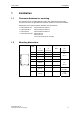
Issue 10/06 1 Installation 1 Installation 1.1 Clearance distances for mounting The inverters can be mounted adjacent to each other. When mounting inverters one above the other, the specified environmental conditions must not be exceeded. Independent of this, these minimum distances must be observed. ¾ ¾ ¾ ¾ 1.
2 Electrical Installation Issue 10/06 2 Electrical Installation 2.
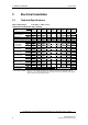
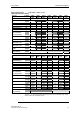
Issue 10/06 2 Electrical Installation Input voltage range 3 AC 200 V – 240 V. ± 10 % (with built in Class A Filter) Order No. 6SE6440- 2AC230CA1 Frame Size Output Rating(CT) Output Power CT Input Current 1) CT-Output Current VT Input Current 1) VT-Output Current Fuse Recommended For UL specified [kW] [hp] [kVA] [A] [A] [A] [A] [A] 3NA 2 Input Cable, min. Input Cable, max. Output Cable, min. Output Cable, max.
2 Electrical Installation Issue 10/06 Input voltage range Order No. 3 AC 200 V – 240 V.
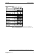
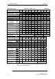
Issue 10/06 2 Electrical Installation Input voltage range 3 AC 380 V – 480 V. ± 10 % (with built in Class A Filter) Order No. 6SE6440- 2AD222BA1 [kW] [hp] [kVA] [A] [A] [A] [A] [A] 3NA 2,2 3,0 4,5 7,5 5,9 – – 16 3805 * Frame Size Output Rating(CT) Output Power CT-Input Current 1) CT-Output Current VT-Input Current 1) VT-Output Current Fuse Recommended For UL specified 3NE 2 Input Cable, min. Input Cable, max. Output Cable, min. Output Cable, max.
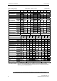
2 Electrical Installation Issue 10/06 Input voltage range Order No. Frame Size Output Rating(CT) Output Power CT-Input Current 1) CT-Output Current VT-Input Current 1) VT-Output Current Fuse Recommended For UL specified 3 AC 380 V – 480 V.
Issue 10/06 2 Electrical Installation Input voltage range Order No.
2 Electrical Installation Issue 10/06 Input voltage range Order No.
Issue 10/06 2.2 2 Electrical Installation Power Terminals You can gain access to the mains and motor terminals by removing the front covers. ¾ ¾ ¾ ¾ ¾ ¾ ¾ ¾ Frame Size A (Fig. 2-1) Frame Sizes B and C (Fig. 2-2) Frame sizes D and E (Fig. 2-3) Frame Size F (Fig. 2-4) Frame Sizes FX and GX (Fig. 2-5) Connection terminals for Frame Sizes A - F (Fig. 2-6) Connection overview for Frame Size FX (Fig. 2-7) Connection overview for Frame Size GX (Fig. 2-8) Frame Size A 1 2 3 4 Fig.
2 Electrical Installation Issue 10/06 Frame Sizes B and C " ! # Fig.
Issue 10/06 2 Electrical Installation Frame Sizes D and E 1 2 3 Fig.
2 Electrical Installation Issue 10/06 Frame Size F 1 2 19 mm AF 3 Fig.
Issue 10/06 2 Electrical Installation Frame Sizes FX and GX 1 2 4 3 Fig.
2 Electrical Installation Issue 10/06 Access to the power supply and motor terminals is possible by removing the front covers. Fig.
Issue 10/06 2 Electrical Installation Hoisting eyes Shield connection Mains cable PE Cable opening for mains conection U1/L1, V1/L2, W1/L3 Cable opening DCPA, DCNA for connection of an external braking unit Mains cable Phase U1/L1, V1/L2, W1/L3 Connection to Y-Capacitor Connection DCPA, DCNA for external braking unit Top adjustment rail Top retaining screw Connection for dv/dt filter DCPS, DCNS Status Display Panel Elektronic box Bottom adjustment rail Bottom retaining screw Fan screws Fan Shield conn
2 Electrical Installation Issue 10/06 Hoisting eyes Shield connection Mains cable PE Cable opening for mains conection U1/L1, V1/L2, W1/L3 Cable opening DCPA, DCNA for connection of an external braking unit Mains cable Phase U1/L1, V1/L2, W1/L3 Connection to Y-Capacitor Connection DCPA, DCNA for external braking unit Top adjustment rail Top retaining screw Connection for dv/dt filter DCPS, DCNS Status Display Panel Elektronic box Bottom adjustment rail Bottom retaining screw Fan screws Fan Shield conn
Issue 10/06 2.3 2 Electrical Installation Control terminals Terminal Designation Function 1 – Output +10 V 2 – Output 0 V 3 ADC1+ Analog input 1 (+) 4 ADC1– Analog input 1 (–) 5 DIN1 Digital input 1 6 DIN2 Digital input 2 7 DIN3 Digital input 3 8 DIN4 Digital input 4 9 – Isolated output +24 V / max.
2 Electrical Installation 2.4 Issue 10/06 Block diagram PE 1/3 AC 200 - 240 V 3 AC 380 - 480 V 3 AC 500 - 600 V L/L1, N/L2 or L/L1, N/L2,L3 or L1, L2, L3 PE +10 V 1 0V 2 ADC1+ 3 ADC1- BOP link A/D 4 RS232 ADC2+ 10 ADC2- A/D 150.
Issue 10/06 3 3 Factory setting Factory setting The MICROMASTER 440 frequency inverter is set in the factory so that it can be operated without any additional parameterization. To do this, the motor parameters set in the factory (P0304, P0305, P0307, P0310), that correspond to a 4-pole 1LA7 Siemens motor, must match the rated data of the connected motor (refer to the rating plate). Further factory setting: ¾ Command sources P0700 = 2 (Digital input, see Fig.
4 Communications Issue 10/06 4 Communications 4.1 Establishing communications MICROMASTER 440 ⇔ STARTER The following optional components are additionally required in order to establish communications between STARTER and MICROMASTER 440: ¾ PC <-> frequency inverter connecting set ¾ BOP if the USS standard values (refer to Section 6.4.1 "Serial Interface (USS)") are changed in the MICROMASTER 440 frequency inverter PC <-> frequency inverter connecting set MICROMASTER 440 USS settings, refer to 6.4.
Issue 10/06 4 Communications AOP as control unit Parameter / Terminal Command source / Frequency setpoint (MOP) AOP on BOP link AOP on COM link P0700 4 5 P1000 P1035 P1036 2032.13 (2032.D) 2032.14 (2032.E) 1 2036.13 (2036.D) 2036.14 (2036.E) Output frequency of the MOP higher Output frequency of the MOP lower Acknowledge fault P2104 2032.7 2036.7 • A fault can be acknowledged via the AOP independently of P0700 or P1000. 4.
5 BOP / AOP (Option) Issue 10/06 BOP / AOP (Option) Buttons and their Functions Panel/ Button Function Effects Indicates Status The LCD displays the settings currently used by the converter. Start converter Pressing the button starts the converter. This button is disabled by default. Activate the button: BOP: P0700 = 1 or P0719 = 10 ... 16 AOP: P0700 = 4 or P0719 = 40 ... 46 on BOP link P0700 = 5 or P0719 = 50 ...
Issue 10/06 5.2 5 BOP / AOP (Option) Changing parameters using as an example P0004 "Parameter filter function" Step Result on the display 1 Press in order to access the parameter 2 Press until P0004 is displayed 3 Press in order to reach the parameter value level 4 Press or 5 Press to acknowledge the value and to save the value 6 The user can only see the command parameters.
6 Commissioning Issue 10/06 6 Commissioning 6.1 Quick commissioning The frequency inverter is adapted to the motor using the quick commissioning function and important technological parameters are set. The quick commissioning shouldn't be carried-out if the rated motor data saved in the frequency inverter (4-pole 1LA Siemens motor, star circuit configuration frequency inverter (FU)specific) match the rating plate data.
Issue 10/06 6 Commissioning FU-spec. P0304 =... P0304 =... Rated motor voltage (Nominal motor voltage [V] from rating plate) The rated motor voltage on the rating plate must be checked, regarding the star/delta circuit configuration to ensure that it matches with the circuit connection configured at the motor terminal board P0305 =... P0305 =... Rated motor current (Nominal motor current [A] from rating plate) P0310 P0304 FU-spec. FU-spec. P0307 P0305 P0307 =... P0307 =...
6 Commissioning Issue 10/06 BOP Terminals USS BOP link P0700 = 2 Sequence control USS COM link CB COM link Motor control Selection of frequency setpoint * (enters the frequency setpoint source) 1 MOP setpoint 2 Analog setpoint 3 Fixed frequency 4 USS on BOP link 5 USS on COM link (control terminals 29 and 30) 6 CB on COM link (CB = communications module) 7 Analog setpoint 2 10 No main setpoint + MOP setpoint 11 MOP setpoint + MOP setpoint 12 Analog setpoint + MOP setpoint 2 ... P1000 =...
Issue 10/06 6 Commissioning P1300 =... Control mode (enters the required control mode) 0 V/f with linear characteristic 1 V/f with FCC 2 V/f with parabolic characteristic 3 V/f with programmable characteristic 5 V/f for textile applications 6 V/f with FCC for textile applications 19 V/f control with independent voltage setpoint 20 Sensorless Vector control 21 Vector control with sensor 22 Sensorless Vector torque-control 23 Vector torque-control with sensor 0 P1500 =...
6 Commissioning 6.2 Issue 10/06 Motor data identification START Factory setting P0625 = ? | Motor temp. - P0625| ≤ 5 °C ? yes no Ambient motor temperature (entered in °C) 20 °C The motor ambient temperature is entered at the instant that motor data is being determined (factory setting: 20 °C). The difference between the motor temperature and the motor ambient temperature P0625 must lie in the tolerance range of approx. ± 5 °C.
Issue 10/06 6 Commissioning The procedure to manually determine the magnetizing current and to re-calculate the equivalent circuit diagram data when the drive is operated with closed-loop vector control (P1300 = 20/21) is shown in the following.
6 Commissioning 6.4 Issue 10/06 Commissioning the application An application is commissioned to adapt/optimize the frequency inverter - motor combination to the particular application. The frequency inverter offers numerous functions - but not all of these are required for the particular application. These functions can be skipped when commissioning the application. A large proportion of the possible functions are described here; refer to the parameter list for additional functions.
Issue 10/06 6.4.3 6 Commissioning Digital input (DIN) Function digital input 1 Terminal 5 1 ON / OFF1 1 Function digital input 7 Via analog input, Terminal 3 0 Digital input disabled 0 P0708 = 0 Function digital input 8 Via analog input, Terminal 10 0 Digital input disabled 0 P0724 = ... Debounce time for digital inputs Defines debounce time (filtering time) used for digital inputs. 0 No debounce time 1 2.5 ms debounce time 2 8.2 ms debounce time 3 12.3 ms debounce time P0725 = ...
6 Commissioning 6.4.4 Issue 10/06 Digital outputs (DOUT) P0731 = ... BI: Function of digital output 1 * Defines source of digital output 1. 52.3 Common Settings: P0732 = ... BI: Function of digital output 2 * Defines source of digital output 2. 52.7 52.0 52.1 52.2 Drive ready Drive ready to run Drive running 0 0 0 P0733 = ... BI: Function of digital output 3 * Defines source of digital output 3. 0.0 r0747 = ...
Issue 10/06 6 Commissioning Selection of frequency setpoint P1000 =... Selection of frequency setpoint 0 No main setpoint 1 MOP setpoint 2 Analog setpoint 3 Fixed frequency 4 USS on BOP link 5 USS on COM link 6 CB on COM link 7 Analog setpoint 2 10 No main setpoint + MOP setpoint 11 MOP setpoint + MOP setpoint 12 Analog setpoint + MOP setpoint 2 ... 6.4.
6 Commissioning 6.4.6 P0756 = ... Issue 10/06 Analog input (ADC) 0 ADC type Defines the analog input type and activates the monitoring function of the analog input.
Issue 10/06 6.4.7 6 Commissioning Analog output (DAC) 21 P0771 = ... CI: DAC Defines function of the 0 - 20 mA analog output.
6 Commissioning 6.4.8 Issue 10/06 Motor potentiometer (MOP) P1031 =... 0 Setpoint memory of the MOP Saves last motor potentiometer setpoint (MOP) that was active before OFF command or power down. 0 MOP setpoint will not be stored 1 MOP setpoint will be stored (P1040 is updated) P1032 =... Inhibit negative MOP setpoints 0 Neg. MOP setpoint is allowed 1 Neg. MOP setpoint inhibited P1040 =... Setpoint of the MOP Determines setpoint for motor potentiometer control. 1 5.
Issue 10/06 6.4.9 6 Commissioning Fixed frequency (FF) P1001 = ... 0.00 Hz Fixed frequency 1 Can be directly selected via DIN1 (P0701 = 15, 16) P1002 = ... 5.00 Hz Fixed frequency 2 Can be directly selected via DIN2 (P0702 = 15, 16) P1003 = ... 10.00 Hz Fixed frequency 3 Can be directly selected via DIN3 (P0703 = 15, 16) P1010 = ... When defining the function of the digital inputs 15.
6 Commissioning 6.4.10 P1058 = ... Issue 10/06 JOG 5.00 Hz JOG frequency right Frequency in Hz when the motor is rotating clockwise in the jog mode. P1059 = ... 5.00 Hz JOG frequency left Frequency in Hz when the motor is rotating counter-clockwise in the jog mode. P1060 = ... 10.00 s JOG ramp-up time Ramp-up time in s from 0 to the maximum frequency (p1082). JOG rampup is limited by p1058 or p1059. P1061 = ... 10.00 s JOG ramp-down time Ramp-down time in s from the maximum frequency (p1082) to 0.
Issue 10/06 6.4.11 6 Commissioning Ramp function generator (RFG) P1091 = ... Skip frequency 1 (entered in Hz) 0.00 Hz Defines skip frequency 1, which avoids effects of mechanical resonance and suppresses frequencies within +/- p1101 (skip frequency bandwidth). P1092 = ... Skip frequency 2 0.00 Hz P1093 = ... Skip frequency 3 0.00 Hz P1094 = ... Skip frequency 4 0.00 Hz P1101 = ... Skip frequency bandwidth (entered in Hz) 2.00 Hz P1120 = ...
6 Commissioning 6.4.12 Issue 10/06 Reference/limit frequencies P1080 = ... 0.00 Hz Min. frequency (entered in Hz) Sets minimum motor frequency [Hz] at which motor will run irrespective of frequency setpoint. If the setpoint falls below the value of p1080, then the output frequency is set to p1080 taking into account the sign. P1082 = ... 50.00 Hz Max. frequency (entered in Hz) Sets maximum motor frequency [Hz] at which motor will run irrespective of the frequency setpoint.
Issue 10/06 6.4.13 P0290 = ... 6 Commissioning Inverter protection Inverter monitoring r0036 i2t P0294 r0037 Heat sink temperature P0292 Inverter overload reaction P0290 A0504 i_max control (U/f) Current control (SLVC, VC) A0505 A0506 F0004 f_pulse control IGBT temperature P0292 P0292 =... 0 Inverter overload reaction Selects reaction of inverter to an internal over-temperature.
6 Commissioning Issue 10/06 A high thermal motor load and when the line supply is frequently switchedout/switched-in requires, for closed-loop vector control − that a KTY84 sensor is used, or − an external 24V power supply voltage is connected P0335 = ... Motor cooling (Selects motor cooling system used) 0 Self-cooled: Using shaft mounted fan attached to motor 1 Force-cooled: Using separately powered cooling fan 2 Self-cooled and internal fan 3 Force-cooled and internal fan 0 P0601 = ...
Issue 10/06 6.4.15 P0400 =... 6 Commissioning Encoder 0 Select encoder type The table shows the values of P0400 as a function of the Selects the encoder type. number of tracks: 0 Inhibited Parameter Terminal Track Encoder output 1 Single-track pulse encoder 2 Two-track pulse encoder single ended P0400 = 1 A For hoisting gear applications (4-quadrant operation!), a 2-track encoder must be used.
6 Commissioning 6.4.16 Issue 10/06 V/f control P1300 =... 0 Control mode The control type is selected using this parameter. For the "V/f characteristic" control type, the ratio between the frequency inverter output voltage and the frequency inverter output frequency is defined. 0 V/f with linear 1 V/f with FCC 2 V/f with parabolic characteristic 3 V/f with programmable characteristic (→ P1320 – P1325) P1310 =... 50.
Issue 10/06 6 Commissioning P1312 =... 0.0 % Starting boost (entered in %) Voltage boost when starting (after an ON command) when using the linear or square-law V/f characteristic as a % relative to P0305 (rated motor current) or P0350 (stator resistance). The voltage boost remains active until 1) the setpoint is reached for the first time and 2) the setpoint is reduced to a value that is less than the instantaneous ramp-function generator output. P1320 =... Programmable V/f freq. 0.0 Hz coord.
6 Commissioning 6.4.17 Issue 10/06 Field-orientated control Limitations To avoid a premature limitation the limits of the torque (P1520, P1521) and power (P1530, P1531) should be set to the maximum value, if the application allows it. p0640 = ... 150.0 % Motor overload factor [%] Defines motor overload current limit in [%] relative to p0305 (rated motor current). Limited to maximum inverter current or to 400 % of rated motor current (p0305), whichever is the lower. p0640max = P1520 = ...
Issue 10/06 6.4.17.
6 Commissioning P1750 = ... Issue 10/06 1 Control word of motor model This parameter controls the operation of the sensorless vector control (SLVC) at very low frequencies.
Issue 10/06 6.4.17.2 6 Commissioning Vector control with encoder (VC) ¾ First step: Parameterizing the speed encoder (refer to Section 6.4.15) ¾ When commissioning Vector Control with encoder-feedback (VC), the drive should be configured for V/f mode (see p1300) first. Run the drive and compare r0061 with r0021 that should agree in: − sign − magnitude (with a deviation of only a few percent) Only if both criteria are fulfilled, change p1300 and select VC (p1300 = 21/23).
6 Commissioning Issue 10/06 Supplementary torque setpoint ¾ In the vector mode – with / without encoder – the speed controller can be subordinate to a constant or variable supplementary torque. ¾ The supplementary setpoint can be used to advantage for hoisting gear with low intrinsic friction when starting in the vertical direction. The supplementary torque setpoint must always be impressed in the hoisting (raising) direction (please observe the sign!).
Issue 10/06 6 Commissioning 6.4.18 Converter-specific Functions 6.4.18.1 Flying start 0 P1200 = ... Flying start Starts inverter onto a spinning motor by rapidly changing the output frequency of the inverter until the actual motor speed has been found.
6 Commissioning 6.4.18.3 Issue 10/06 Holding brake ¾ Series / commissioning for hazardous loads − lower the load to the floor − when replacing the frequency inverter, prevent (inhibit) the frequency inverter from controlling the motor holding brake (MHB) − secure the load or inhibit the motor holding brake control (so that the brake cannot be controlled) and then – and only then – carry-out quick commissioning / parameter download using the PC-based tool (e.g.
Issue 10/06 6 Commissioning 52.3 P0731=52.C BI: Fct digital output 1 Defines the source for digital output 1. NOTE The brake relay can also be controlled from another digital output (if this is available) or using a distributed I/O module. Analog to DOUT 1, it should be guaranteed that the I/Os are controlled by the status bit “MHB active”. P0748 = 0 0 Inverting digital outputs This parameter allows the signals to be output to be inverted. Frequent settings: 52.0 52.1 52.2 52.3 52.4 52.5 52.6 52.7 52.
6 Commissioning 6.4.18.4 P1230 = ... Issue 10/06 DC brake BI: Enabling the DC brake This enables DC braking using a signal that was used from an external source. The function remains active as long as the external input signal is active. DC braking causes the motor to quickly stop by injecting a DC current BI: Enable DC brk. 1 P1230.
Issue 10/06 6 Commissioning 2 ON OFF1/OFF3 t P0347 OFF2 t ⏐f⏐ OFF ramp OFF2 P1234 DC braking OFF2 t DC braking active r0053 1 Bit00 0 P1234 =... 6.4.18.5 P1236 =... t P1233 650 Hz DC braking start frequency (entered in Hz) Sets the start frequency for the DC brake. Compound braking 0% Compound braking current (entered in %) Defines DC level superimposed on AC waveform after exceeding DC-link voltage threshold of compound braking.
6 Commissioning 6.4.18.6 Issue 10/06 Dynamic braking The following settings should always be made: ¾ The Vdc_max controller de-activated P1240 = 0 ¾ The compound brake de-activated P1236 = 0 ¾ Resistor brake activated P1237 > 0 P1237 = ... (def.: P1240 = 1) (def.: P1236 = 0) (def.: P1237 = 0) 0 Dynamic braking Dynamic braking is activated using parameter P1237 – the nominal (rated) duty cycle as well as the switch-in duration of the braking resistor are also defined.
Issue 10/06 6.4.18.8 6 Commissioning Load torque monitoring This function monitors the transmission of force between a motor and driven load within a defined frequency range. Typical applications include, for example, detecting when a transmission belt breaks or detecting when a conveyor belt is in an overload condition. For the load torque monitoring, the actual frequency/torque actual value is compared to a programmed frequency/torque characteristic (refer to P2182 – P2190).
6 Commissioning Issue 10/06 |Torque| [Nm] P1080 Min. frequency P1082 Max.
Issue 10/06 6.4.18.9 6 Commissioning PID controller P2200 =... 0.0 BI: Enable PID controller PID mode Allows user to enable/disable the PID controller. Setting to 1 enables the PID controller. Setting 1 automatically disables normal ramp times set in P1120 and P1121 and the normal frequency setpoints. r2251 =... PID mode Configuration of PID controller. 0 PID as setpoint 1 PID as trim P2253 =... CI: PID setpoint Defines setpoint source for PID setpoint input. P2254 =... 0.
6 Commissioning Issue 10/06 Controller structures These structures are selected using parameters P2200 and P2251.
Issue 10/06 6 Commissioning PID cancer control PID SUM P2253 USS COM link CB COM link P2264 ADC2 P2200 Parameter P1070 P2200 PID PT1 P2269 USS BOP link PID RFG − ∆PID P2265 P2271 BI: Enable PID controller CI: PID setpoint Fixed setpoint (FF) 1050 MOP 755.0 Analog input 1 2015.1 USS on BOP link 2019.1 USS on COM link 2050.
6 Commissioning Issue 10/06 6.4.18.10 Positioning down ramp P0500 = ... P2481 = ... 0 Technological application Selects technological application. Sets control mode (P1300). 0 Constant torque 1 Pumps and fans 3 Simple Positioning 1.00 Gearbox ratio input Defines the ratio between number of motor shaft revolutions to equal one revolution of the gearbox output shaft. Motor Load Gear Ü nMotor n Load Ü= P2482 = ... P2484 = ... Motor revolutions Load revolutions = P2481 P2482 1.
Issue 10/06 6 Commissioning 6.4.18.11 Free function blocks (FFB) P2800 =... 0 Enable FFBs Parameter P2800 is used to activate all free function blocks (generally, P2800 is set to 1). Possible settings: 0 Inhibited 1 Enabled P2801 =... 0.0 Activate FFBs Parameter P2801 is used to individually enable (activate) the free function blocks P2801[0] to P2801[16] (P2801[x] > 0). Further, parameters P2801 and P2802 are used to define the chronological sequence of all of the function blocks.
6 Commissioning Issue 10/06 FFB Input parameters Output parameters AND1 AND2 AND3 P2810[2] P2812[2] P2814[2] BI: AND 1 BI: AND 2 BI: AND 3 r2811 r2813 r2815 BO: AND 1 BO: AND 2 BO: AND 3 – – – OR1 OR2 OR3 P2816[2] P2818[2] P2820[2] BI: OR 1 BI: OR 2 BI: OR 3 r2817 r2819 r2821 BO: OR 1 BO: OR 2 BO: OR 3 – – – XOR1 XOR2 XOR3 P2822[2] P2824[2] P2826[2] BI: XOR 1 BI: XOR 2 BI: XOR 3 r2823 r2825 r2827 BO: XOR 1 BO: XOR 2 BO: XOR 3 – – – NOT1 NOT2 NOT3 P2828 P2830 P2832 BI: NOT 1 BI: NOT
Issue 10/06 6.4.19 6 Commissioning Data sets For many applications it is beneficial to have the possibility to change several parameter settings simultaneous during operation or in the state ready to run with an external signal. By indexing it is possible to set a parameter to several values which can be activated by data set change-over. There are the following data sets: ¾ CDS Command Data Set ¾ DDS Drive Data Set Command data set (CDS) P0810 =...
6 Commissioning Issue 10/06 Drive data set (DDS) P0820 = ... 0 Drive data set (DDS) bit 0 Selects the command source from which bit 0 should be read-out to select a drive data set. Operation Ready t Select DDS BI: DDS bit 1 P0821 (0:0) CO/BO: Act CtrlWd2 3 r0055 .05 r0055 .05 2 BI: DDS bit 0 CO/BO: Act CtrlWd2 1 P0820 (0:0) Active DDS r0051[1] r0055 .04 r0055 .04 0 t Changeover time approx. 50 ms Changeover time approx. 50 ms 3 2 CO: Active DDS r0051 .
Issue 10/06 6 Commissioning Example: 1. Commissioning steps with a motor: − Carry-out commissioning at DDS1. − Connect P0820 (P0821 if required) to the DDS changeover source (e.g. using DIN 4: P0704[0] = 99, P0820 = 722.3). − Copy DDS1 to DDS2 (P0819[0] = 0, P0819[1] = 1, P0819[2] = 2). − Adapt DDS2 parameters (e.g. ramp-up / ramp-down times P1120[1] and P1121[1]). Sequence control SUM setpoint ADC AFM Motor control RFG Gating unit DIN M P0820 = 722.
6 Commissioning 6.4.20 Issue 10/06 Diagnostic parameters r0021 CO: Act. filtered frequency Displays actual inverter output frequency (r0021) excluding slip compensation, resonance damping and frequency limitation. r0022 Act. filtered rotor speed Displays calculated rotor speed based on inverter output frequency [Hz] x 120 / number of poles. r0022 [1/min] = r0021 [Hz] ⋅ r0032 60 r0313 CO: Act. filtered power Displays motor power (power output at the motor shaft).
Issue 10/06 r0054 r0063 6 Commissioning CO/BO: Control word 1 Displays the first control word (STW) of the frequency inverter and can be used to display the active commands.
6 Commissioning r1079 Issue 10/06 CO: Selected frequency setpoint Displays the selected frequency setpoint. The following frequency setpoints are displayed: • r1078 total setpoint (HSW + ZUSW) • P1058 JOG frequency, clockwise • P1059 JOG frequency, counter-clockwise. JOG Setpoint source Reverse r1079 r1078 74 P1110 P1091 Inhibit neg. freq. setpoint Skip frequency r1114 P1080 P1082 P1120 P1135 ... IfI Motor control RFG r0020 r1170 r1119 r1114 CO: Freq. setpoint after dir. ctrl.
Issue 10/06 6.5 6 Commissioning Series commissioning An existing parameter set can be transferred to a MICROMASTER 440 frequency inverter using STARTER or DriveMonitor (refer to Section 4.1 "Establishing communications MICROMASTER 440 ⇔ STARTER"). Typical applications for series commissioning include: 1. If several drives are to be commissioned that have the same configuration and same functions. A quick / application commissioning (first commissioning) must be carried-out for the first drive.
7 Displays and messages Issue 10/06 7 Displays and messages 7.1 LED status display LEDs for indicating the drive state OFF ON approx. 0.3 s, flashing approx.
Issue 10/06 7.2 7 Displays and messages Fault messages and Alarm messages Fault Significance Alarm Significance F0001 Overcurrent A0501 Current Limit F0002 Overvoltage A0502 Overvoltage limit F0003 Undervoltage A0503 Undervoltage Limit F0004 Inverter Overtemperature A0504 Inverter Overtemperature A0505 Inverter I2t F0005 Inverter I t F0011 Motor Overtemperature I2t A0506 Inverter Duty Cycle F0012 Inverter temp.
Information about MICROMASTER 440 is also available from: Regional Contacts Please get in touch with your contact for Technical Support in your Region for questions about services, prices and conditions of Technical Support. Central Technical Support The competent consulting service for technical issues with a broad range of requirements-based services around our products and systems. Europe / Africa Tel: +49 (0) 180 5050 222 Fax: +49 (0) 180 5050 223 Email: adsupport@siemens.